Control apparatus of internal combustion engine

Inactive Publication Date: 2006-05-04
TOYOTA JIDOSHA KK
View PDF7 Cites 9 Cited by
  • Summary
  • Abstract
  • Description
  • Claims
  • Application Information

AI Technical Summary

Benefits of technology

[0012] In the above-described construction, when the fuel vapor concentration is high, that is, when it is necessary to promptly discharge accumulated fuel vapor from the fuel vapor treatment system, at least one of the lift amount and the working angle of the intake valve is increased. If the lift amount / working angle of the intake valve is increased in this manner, the degree of opening of the throttle valve is decreased in order to keep the amount of intake air constant. As a result, the pressure in the intake passageway downstream of the throttle valve is reduced, so that it becomes possible to promptly release fuel vapor from the fuel vapor treatment system. Furthermore, when the fuel vapor concentration is low, the lift amount or the working angle of the intake valve can be reduced. Therefore, fuel economy can be improved.
[0021] Generally, if the lift amount or the working angle is merely increased, the duration in which both the intake valve and the exhaust valve are open, that is, a generally-termed valve overlap, becomes unnecessarily long. Therefore, in that case, the amount of exhaust gas returned from the exhaust passageway of the internal combustion engine to the combustion chamber, that is, the generally-termed amount of internal EGR, is increased significantly, which may result in an unstable state of engine operation. However, the above-described construction makes it possible to substantially avoid unnecessary increases of the valve overlap and therefore stabilizes the engine operation state.

Problems solved by technology

Therefore, the release of collected fuel vapor into the intake passageway sometimes becomes difficult, and securement of a necessary amount of release may become impossible.

Method used


Image

  • Control apparatus of internal combustion engine
  • Control apparatus of internal combustion engine
  • Control apparatus of internal combustion engine

Examples


Embodiment Construction

[0030] In the following description, the invention will be described in more detail in terms of exemplary embodiments.

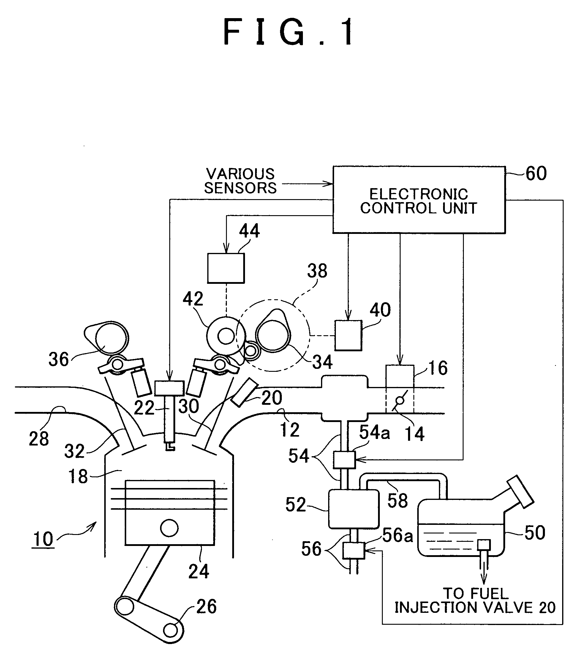
[0031]FIG. 1 illustrates the overall construction of a control apparatus for internal combustion engine in accordance with an embodiment.

[0032] As shown in FIG. 1, an intake passageway 12 of an internal combustion engine 10 is provided with a throttle valve 14. A throttle motor 16 is connected to the throttle valve 14. Through the drive control of the throttle motor 16, the degree of opening of the throttle valve 14 (throttle opening amount TA) is adjusted, thereby adjusting the amount of intake air taken fed to a combustion chamber 18 through the intake passageway 12 (amount of intake air GA). Furthermore, the intake passageway 12 is provided with a fuel injection valve 20. This fuel injection valve 20 injects fuel into the intake passageway 12.

[0033] In the combustion chamber 18 of the internal combustion engine 10, a mixture formed by intake air and injected fu...


PUM


Abstract

a control apparatus for an internal combustion engine provided with a fuel vapor treatment system according to the invention includes a controller that discharges fuel vapor into an intake passageway by using the intake negative pressure, and which adjusts the amount of the intake air through the cooperative control of a variable control of at least one of the lift amount of an intake valve and the working angle of the intake valve, and a control of the degree of opening of a throttle valve. In addition, the control apparatus executes the variable control so that at least one of the lift amount and the working angle of the intake valve changes in accordance with the fuel vapor concentration in the fuel vapor treatment system.

Description

INCORPORATION BY REFERENCE [0001] The disclosure of Japanese Patent Application No. 2004-317201 filed on Oct. 29, 2004, including the specification, drawings and abstract is incorporated herein by reference in its entirety. BACKGROUND OF THE INVENTION [0002] 1. Field of the Invention [0003] The invention relates to a control apparatus for an internal combustion engine having a fuel vapor treatment system that adjusts the amount of intake air through the cooperative control of the variable control of either or both of the lift amount of an intake valve and the working angle of the intake valve with the control in the degree of opening of a throttle valve. [0004] 2. Description of the Related Art [0005] As a system adopted in internal combustion engines of vehicles and the like, systems that provide for the variable control of the lift amount and the working angle of engine valves (intake-exhaust valves) in accordance with the engine operation condition have recently been put into pra...

Claims


Application Information

Patent Timeline
IPC IPC(8): F02D13/02
CPCF02D13/0215F02D13/023F02D13/0238F02D13/0261F02D41/0002F02D41/003F02D41/0045F02D41/006F02D2041/001F02D2041/002F02M25/0752Y02T10/42Y02T10/18F02M26/01Y02T10/12Y02T10/40
Inventor MIYANOO, YUUJIHIROSE, KIYOO
Owner TOYOTA JIDOSHA KK
Why Eureka
Try Eureka