Eureka AIR delivers breakthrough ideas for toughest innovation challenges, trusted by R&D personnel around the world.

Control apparatus for vehicle

a technology for controlling apparatus and vehicle, applied in the direction of electric control, control devices, vehicle components, etc., can solve the problems of affecting the comfort of passengers, so as to achieve the effect of suppressing discomfort for passengers

Active Publication Date: 2006-04-27
TOYOTA JIDOSHA KK
View PDF4 Cites 12 Cited by
  • Summary
  • Abstract
  • Description
  • Claims
  • Application Information

AI Technical Summary

Benefits of technology

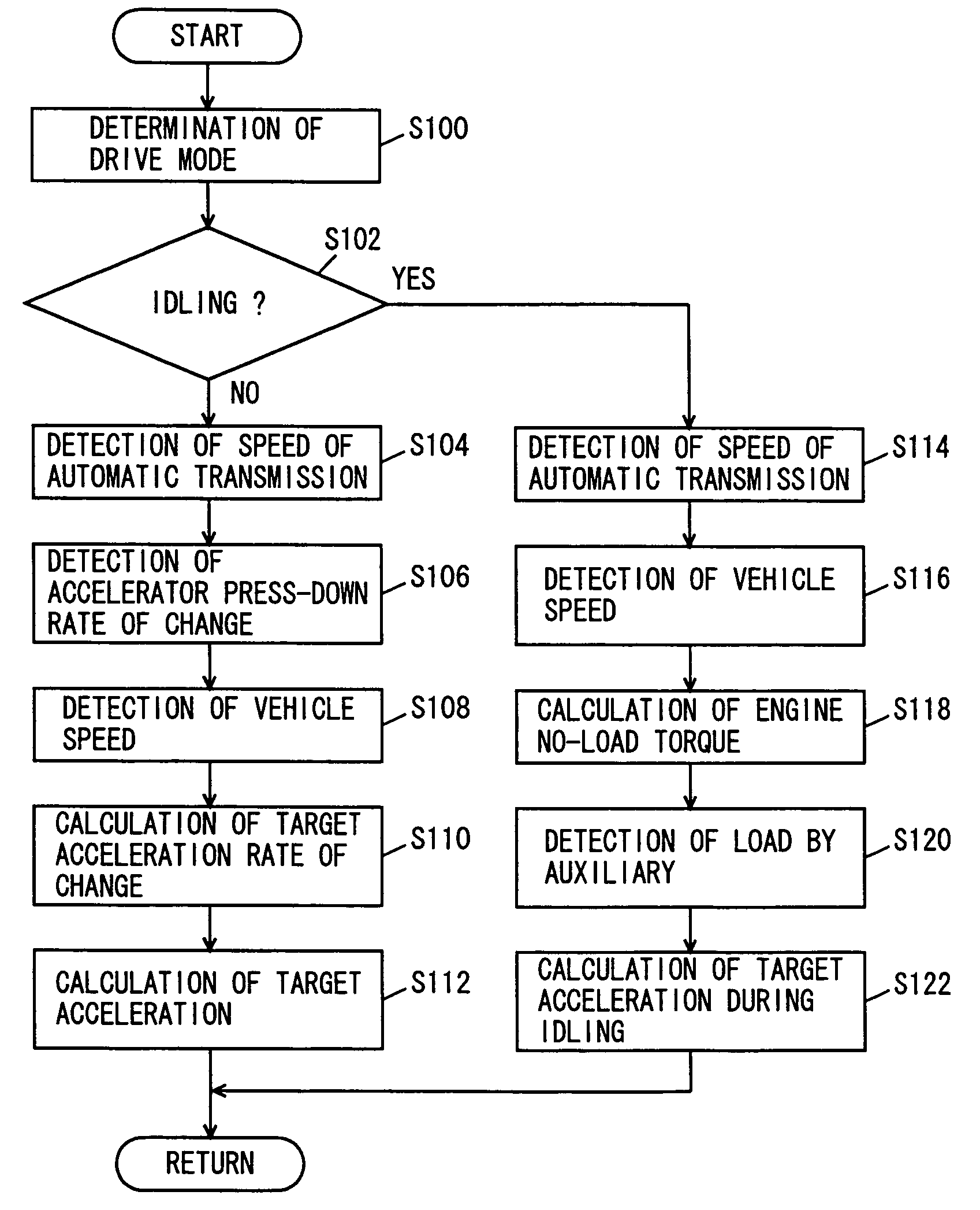
The present invention provides a control apparatus for a vehicle that can accelerate while suppressing discomfort to the occupant. The apparatus includes a detection unit for detecting the rate of change of the accelerator press-down, a setting unit for setting the rate of change of target acceleration, a calculation unit for calculating the vehicle target acceleration based on the set target acceleration rate of change, and a control unit for controlling the driving force of the vehicle based on the calculated target acceleration. The target acceleration is calculated by integrating the rate of change of the target acceleration that is set based on the rate of change of accelerator press-down. The control apparatus can also set the rate of change of target acceleration based on the selected running mode, and can detect and inhibit the engine idling state. The target acceleration in an idling state is determined based on the vehicle speed and gear ratio. The technical effect of the invention is to provide a smooth acceleration experience for the occupant while suppressing discomfort.

Problems solved by technology

In other words, the driver will sense discomfort if the acceleration is too great or too small.
The driving force control device disclosed in Japanese Patent Laying-Open No. 10-009018 is disadvantageous in that the acceleration property may not be rendered gentle in the region where the changing property of the target driving force is not limited, leading to the possibility of applying discomfort to the occupant caused by the abrupt acceleration.
Further, if the changing rate of the target driving force is limited, the target driving force per se will be also limited correspondingly.
There was a problem of applying discomfort to the occupant of the vehicle.

Method used


Image

  • Control apparatus for vehicle
  • Control apparatus for vehicle
  • Control apparatus for vehicle

Examples


Embodiment Construction

[0023] An embodiment of the present invention will be described hereinafter with reference to the drawings. In the description set forth below, the same elements have the same reference characters allotted. Their designation and function are also the same. Therefore, details of the description thereof will not be repeated.

[0024] The power train of a vehicle including a control apparatus of the present embodiment will be described with reference to FIG. 1. The control apparatus for a vehicle according to the present invention is realized by a program executed by an ECU (Electronic Control Unit) 1000 shown in FIG. 1. The present embodiment will be described in which an automatic transmission with a gear type transmission includes a torque converter as a hydraulic coupling. It will be understood that the present invention is not limited to an automatic transmission with a gear type transmission mechanism. For example, a continuously variable transmission such as of the belt type may b...


PUM


Abstract

An ECT_ECU executes a program including the step of identifying the drive mode, the step of determining whether the engine is in an idling state or not, the step of detecting the speed of an automatic transmission when not in an idling state, the step of detecting an accelerator press-down rate of change, the step of detecting vehicle speed, the step of calculating a target acceleration rate of change of the vehicle based on the drive mode, speed of the automatic transmission, accelerator press-down rate of change, and vehicle speed, and the step of calculating the target acceleration by integrating the calculated target acceleration rate of change with respect to time.

Description

[0001] This nonprovisional application is based on Japanese Patent Application No. 2004-309913 filed with the Japan Patent Office on Oct. 25, 2004 the entire contents of which are hereby incorporated by reference. BACKGROUND OF THE INVENTION [0002] 1. Field of the Invention [0003] The present invention relates to a control apparatus for a vehicle, particularly a control apparatus for a vehicle calculating target acceleration to have the driving force controlled based on the calculated target acceleration. [0004] 2. Description of the Background Art [0005] It is conventionally known that the acceleration of a vehicle greatly affects the drivability. In other words, the driver will sense discomfort if the acceleration is too great or too small. It is therefore necessary to appropriately control the acceleration of a vehicle. [0006] Japanese Patent Laying-Open No. 10-009018 discloses a driving force control device for a vehicle that can provide an appropriate feel of acceleration. The ...

Claims


Application Information

Patent Timeline
Patent Type & Authority Applications(United States)
IPC IPC(8): B60K41/04B60W10/00F02D29/00F02D45/00
CPCB60W30/18054B60W30/1884Y10T477/679Y10T477/675F02D11/105
Inventor OGAWA, HIROYUKI
Owner TOYOTA JIDOSHA KK
Why Eureka
Eureka Blog
Learn More