
Engine power assembly

a technology of power assembly and engine, which is applied in the direction of engine cooling apparatus, liquid cooling, cylinders, etc., can solve the problems of accelerating gasket wear, affecting the performance of the engine, so as to minimize the aforementioned wear of the cylinder liner

Inactive Publication Date: 2006-04-27
GENERAL ELECTRIC CO
View PDF15 Cites 7 Cited by
  • Summary
  • Abstract
  • Description
  • Claims
  • Application Information

AI Technical Summary

Benefits of technology

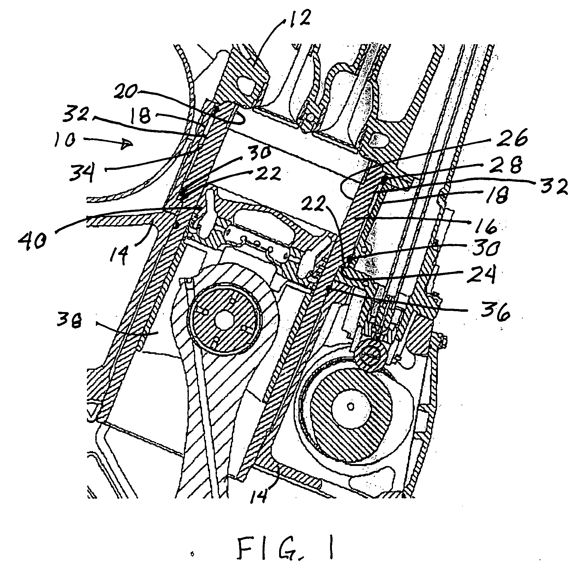
[0011] The present invention includes an engine power assembly having a cylinder head, an engine frame, a cylinder liner, and a water jacket. The cylinder liner is supported by abutting the water jacket, which in turn abuts the engine frame. The cylinder liner does not directly abut the engine frame. This elimination of direct abutment of the cylinder liner against the engine frame minimizes the aforementioned wear of the cylinder liner.
[0012] Also, a coolant passage is provided between the water jacket and the cylinder liner, adjacent the top end of the cylinder liner at the topmost position of the top piston ring. This maximizes cooling by circulating coolant against the outer surface of the cylinder liner at the same height as the location of the initiation of combustion, which occurs at the top of the cylinder above the topmost position of the top piston ring.
[0014] Finally, seals are provided at the upper and lower portions of the cylinder liner, above and below the coolant passage. The upper seal seals between the cylinder liner and the water jacket, while the lower seal seals between the cylinder liner and the engine frame. A fire ring is provided between the combustion chamber and the head gasket, thus protecting the head gasket from accelerated wear by direct exposure to the high temperature products of combustion.

Problems solved by technology

There are several problems related to the way in which an engine frame, cylinder head, cylinder liner, and water jacket are assembled, in any internal combustion engine which utilizes a separate cylinder liner.
One of these problems is the leakage of coolant.
The mating surfaces between an engine block or cylinder liner and the related cylinder head are typically subject to some leakage of products of combustion, as well as coolant, especially in high compression diesel engines used for locomotive applications.
These surfaces are commonly mated with a head gasket in between, and the head gasket is often subject to exposure to high temperature and high pressure combustion products from the combustion chamber, accelerating gasket wear and the attendant leakage of coolant and combustion products.
Flow passages between this area and the cylinder head are subject to some leakage of coolant, especially where the coolant passages are sealed only by the head gasket.
This is because the head gasket is subjected to the aforementioned high combustion pressure and temperature, and the gasket can deteriorate as a result of this pressure and temperature.
This deterioration of the head gasket can ultimately result in coolant leakage.
Another problem associated with this type of engine is the inefficient removal of excess heat from the area surrounding the combustion chamber, which can result in hot spots, stress concentrations, and accelerated component wear.
In providing flow of the coolant to the area surrounding the cylinder liner, if the coolant flow is restricted to contact only with the portion of the cylinder liner below the topmost position of the top piston ring, the removal of excess heat from the combustion chamber can be inefficient.
So, a lower efficiency of heat removal results from circulating the coolant in contact with a relatively low portion of the outer surface of the cylinder liner.
A further problem associated with this type of engine is accelerated wear of the structural components of the engine, which can result from the repetitive loads imposed on the components by repetitive firing of the cylinder.
The cylinder liner can experience advanced wear where it abuts the engine frame, because of repetitive combustion loads on the cylinder liner.

Method used


Image

  • Engine power assembly
  • Engine power assembly
  • Engine power assembly

Examples


Embodiment Construction

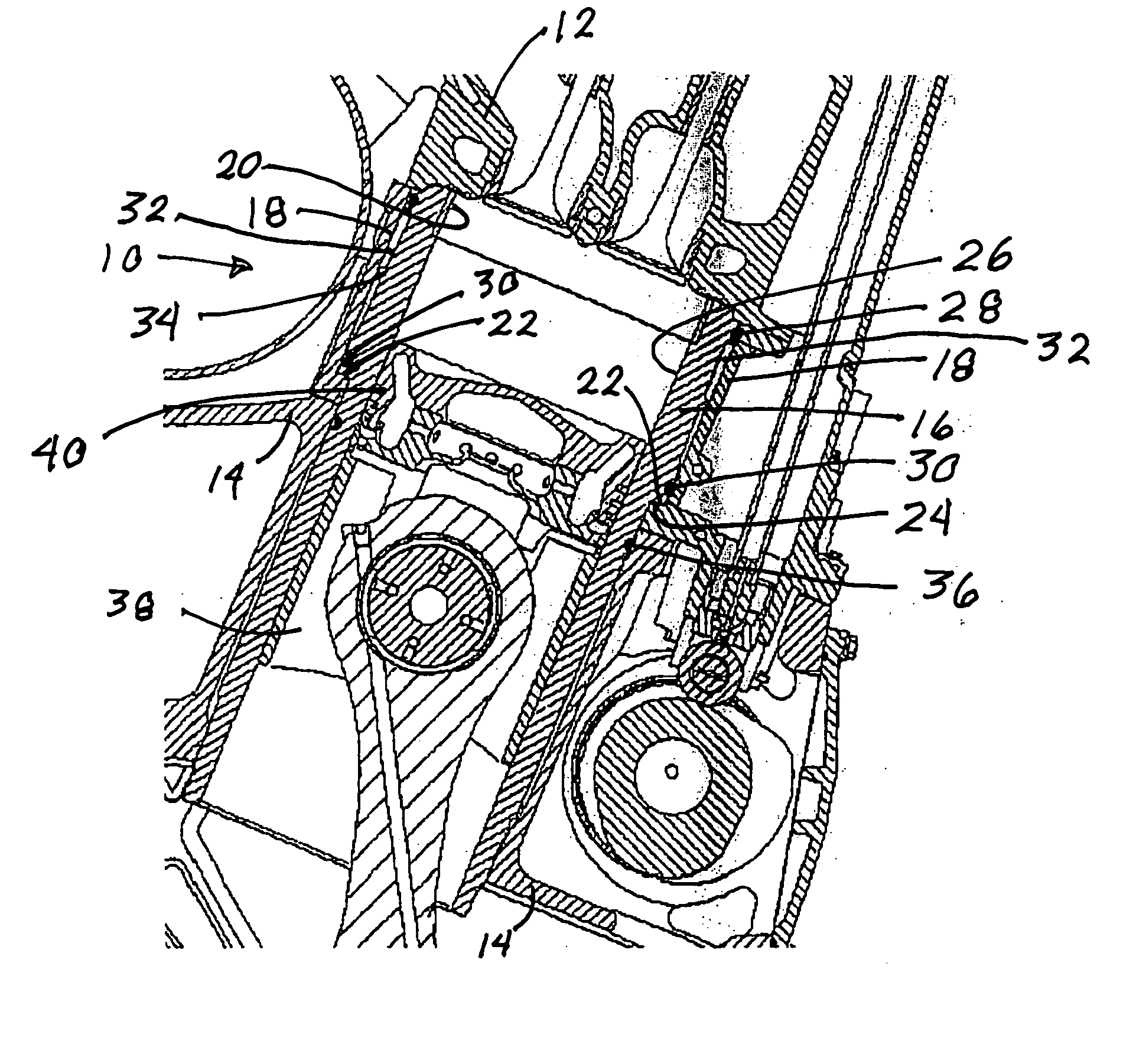
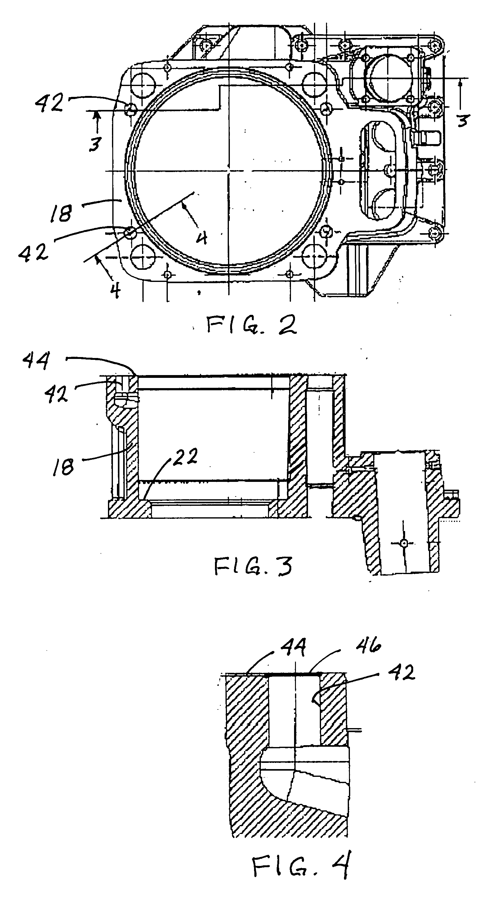
[0020] As shown in FIG. 1, a first embodiment of the apparatus 10 of the present invention includes a cylinder head 12, an engine frame 14, a cylinder liner 16, a strongback or water jacket 18, and a fire ring 20. An upwardly facing flange 22 can be provided on the internal surface of the water jacket 18, better seen in FIG. 3, and a downwardly facing shoulder 24 can be provided on the external surface of the cylinder liner 16. The shoulder 24 is designed to abut the flange 22, in order to support the cylinder liner 16 from the water jacket 18. The water jacket 18 is in turn supported by the engine frame 14. This avoids direct support of the cylinder liner 16 by the engine frame 14, thereby minimizing wear of the cylinder liner 16.

[0021] The fire ring 20 is provided at the joint between the cylinder liner 16 and the cylinder head 12, to protect the head gasket from damage by exposure to hot combustion gases. A piston 38 is shown at a lower position, for the sake of clarity. In oper...


PUM


Abstract

A locomotive diesel engine, having a cylinder liner and a separate water jacket surrounding the cylinder liner, with a portion of the water jacket being positioned between the cylinder liner and the engine frame, where the cylinder liner is supported by the water jacket. An external shoulder on the cylinder liner can be supported by an internal flange in the water jacket, thereby eliminating direct contact between the cylinder liner and the engine frame. A coolant passage can be provided between the water jacket and the cylinder liner, at a point adjacent the topmost position of the top piston ring. An upper liner seal can be provided between the cylinder liner and the water jacket, above the coolant passage, and a lower liner seal can be provided between the cylinder liner and the engine frame, below the coolant passage. Coolant ports can be provided for coolant flow directly between the cylinder head and the water jacket, with seals in the coolant ports to seal the coolant, independently of the head gasket.

Description

CROSS REFERENCE TO RELATED APPLICATIONS [0001] Not Applicable STATEMENT REGARDING FEDERALLY SPONSORED RESEARCH OR DEVELOPMENT [0002] Not Applicable BACKGROUND OF THE INVENTION [0003] 1. Field of the Invention [0004] This invention is in the field of locomotive diesel engines, [0005] specifically as it relates to the engine components involved in coolant flow and heat removal from the structures surrounding the combustion chamber. [0006] 2. Background Art [0007] There are several problems related to the way in which an engine frame, cylinder head, cylinder liner, and water jacket are assembled, in any internal combustion engine which utilizes a separate cylinder liner. One of these problems is the leakage of coolant. The mating surfaces between an engine block or cylinder liner and the related cylinder head are typically subject to some leakage of products of combustion, as well as coolant, especially in high compression diesel engines used for locomotive applications. These surfaces...

Claims


Application Information

Patent Timeline
Patent Type & Authority Applications(United States)
IPC IPC(8): F02F1/16
CPCF01P3/02F01P11/04F01P2003/021F01P2003/024F02F1/16F02F2001/106F02F1/163
Inventor FLYNN, PAUL LLOYDLEBEGUE, JEFFREY SCOTTDOWELL, JOHN PATRICKRECORD, BARRY
Owner GENERAL ELECTRIC CO
Learn More