
Management of relationships between database tables

a database table and relationship technology, applied in relational databases, database models, instruments, etc., can solve the problems of false referential integrity constraints, time-consuming process of creating such relations, and multiple tables being joined in multiple ways,

Active Publication Date: 2006-04-20
DOMO
View PDF18 Cites 50 Cited by
  • Summary
  • Abstract
  • Description
  • Claims
  • Application Information

AI Technical Summary

Benefits of technology

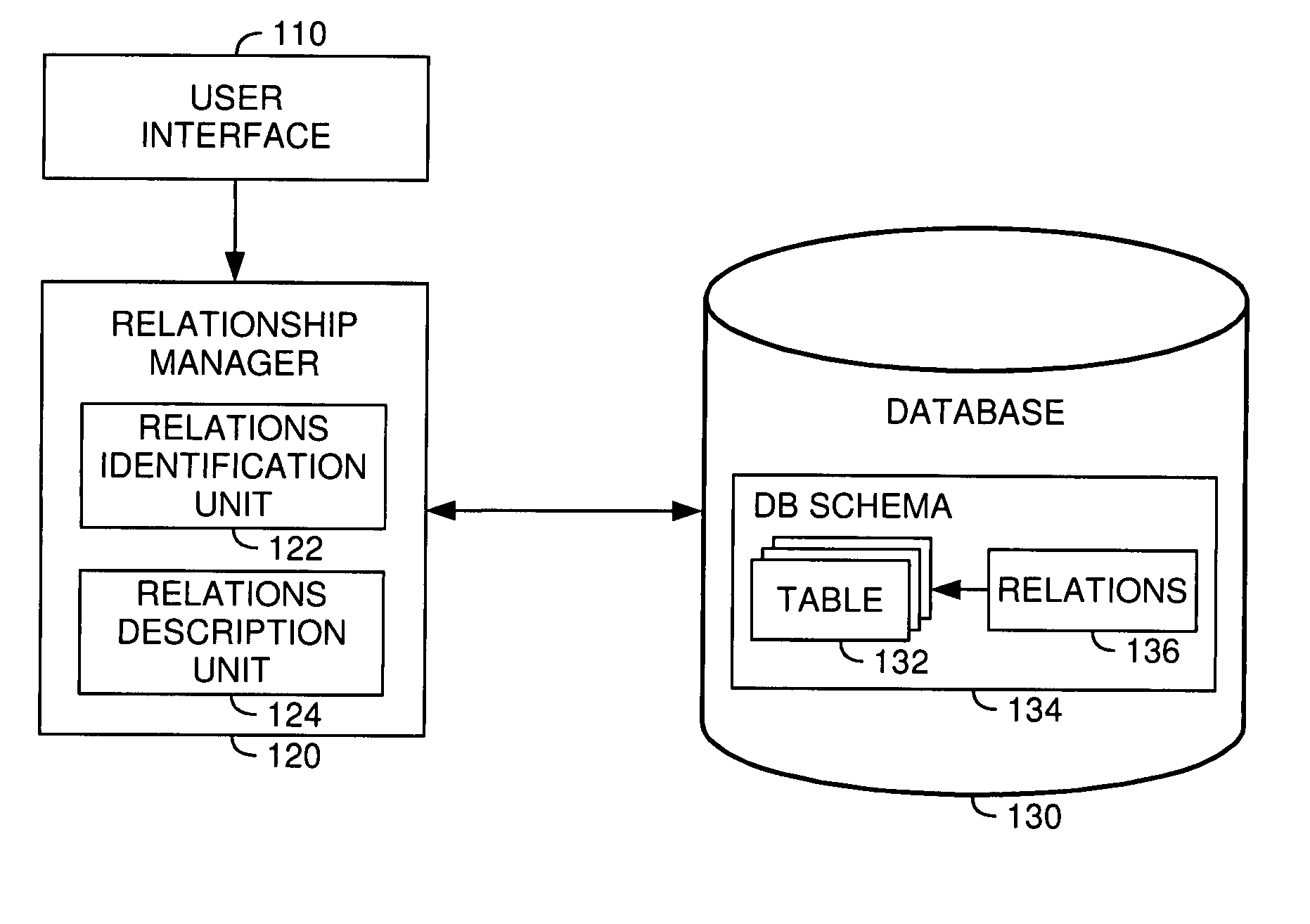
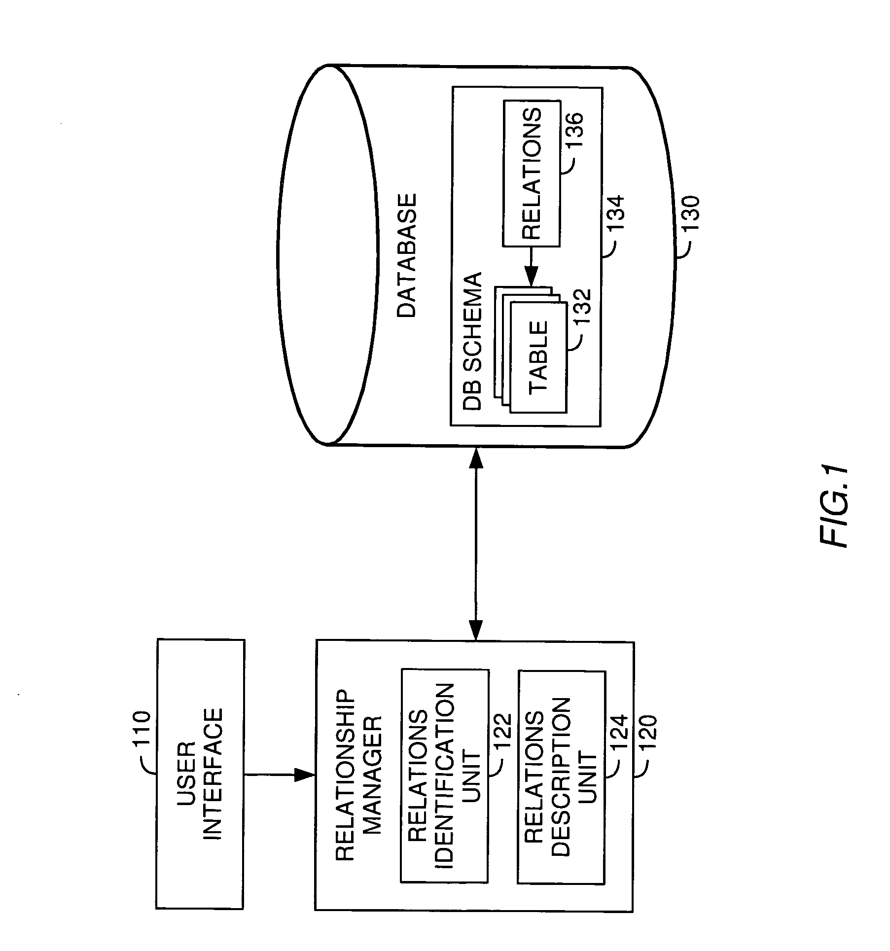
"The present invention is about managing relationships between database tables. One embodiment provides a method for identifying relationships between tables in a database. Another embodiment provides a computer-readable medium containing a program for identifying relationships between tables in a database. A system comprising a database, a relations identification user interface, and a relationship manager is also provided. The technical effect of the invention is that it allows users to easily identify and describe relationships between tables in a database, which can improve data management and data analysis."

Problems solved by technology

One difficulty when defining relations between different database tables is that the process of creating such relations is often time consuming, especially if a given relational database includes a great number of database tables.
However, with so many relations to create it is quite easy for the administrator or developer to make a mistake causing relations to be missing or tables being joined in multiple ways.
Furthermore, if primary keyforeign key relationships are used to create the relations, false referential integrity constraints may occur at a later stage if the primary key column is deleted.
Such missing or wrong relations may then lead to incorrect query results as tables cannot be linked correctly in execution of a given query.

Method used


Image

  • Management of relationships between database tables
  • Management of relationships between database tables
  • Management of relationships between database tables

Examples


Embodiment Construction

Introduction

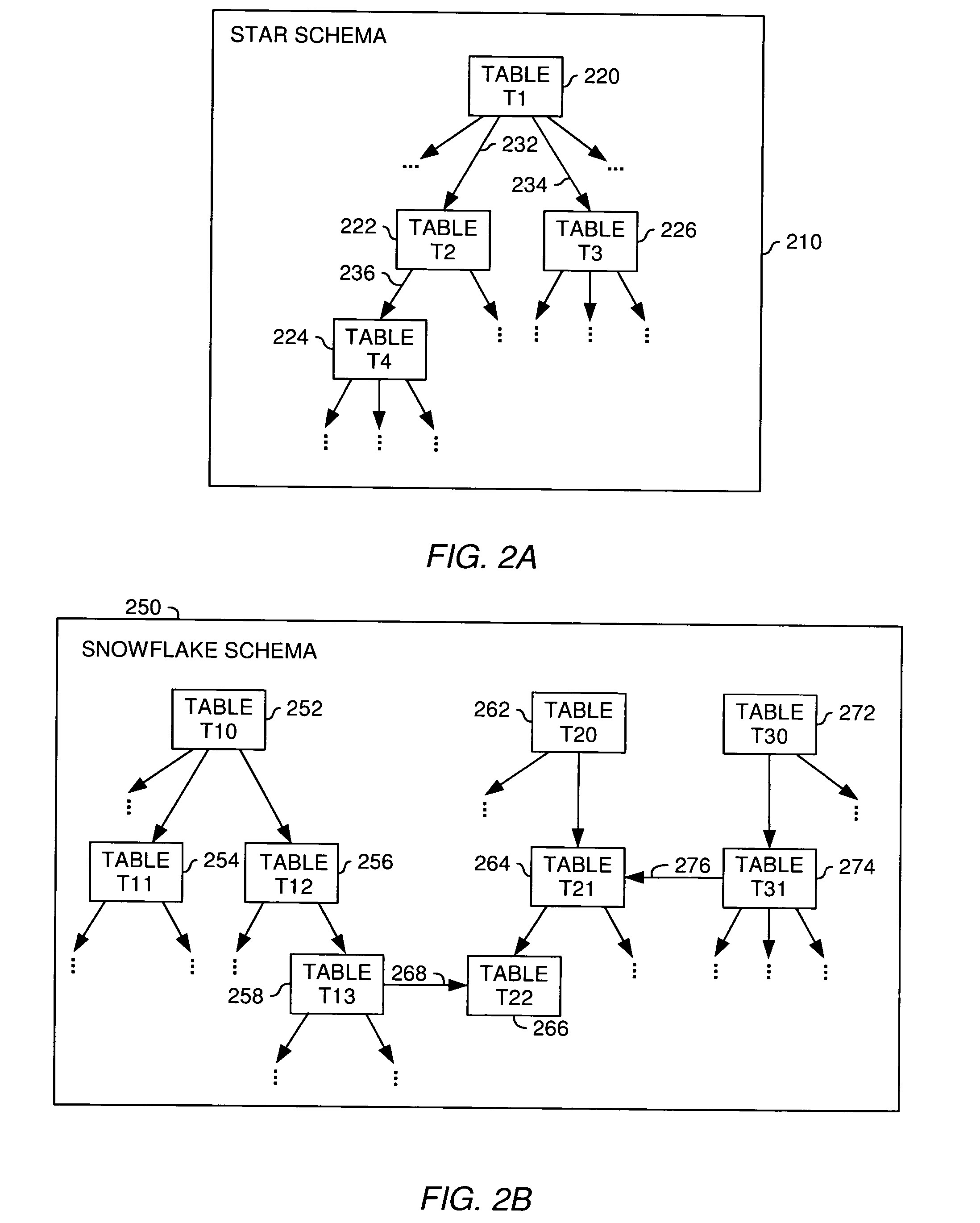
[0024] The present invention is generally directed to a method, system and article of manufacture for managing relationships between database tables and, more particularly, for identifying and accurately describing relationships between tables in a database. According to aspects of the invention, the database is organized in a star schema or a snowflake schema. A star schema is a database schema having a single root table connected to a multiplicity of linked tables. A snowflake schema corresponds to several connected star schemas.

[0025] In one embodiment, relationships between different tables of a database are identified by a user via a corresponding user interface. More specifically, using the user interface the user can select a plurality of tables from the database. At least a portion of the selected plurality of tables includes information that is related to a common subject. Accordingly, the at least one portion of the plurality of tables can be organized into a...


PUM


Abstract

A method, system and article of manufacture for managing relationships between database tables and, more particularly, for identifying and accurately describing relationships between tables in a database. One embodiment provides a method for identifying relationships between tables in a database. The method comprises receiving user input selecting a plurality of tables from the database. The plurality of tables is organized into a logical island defining a logical unit related to a particular logical entity. The method further comprises receiving user input identifying, for each of the plurality of tables, a table column containing information that identifies the particular logical entity in the table, whereby the identified table columns of different tables define logical relationships between the different tables in the logical island. On the basis of the identified table columns, relations specifications are created which describe the logical relationships between the different tables in the logical island.

Description

CROSS-RELATED APPLICATION [0001] This application is related to the following commonly owned application: U.S. patent application Ser. No. 10 / 083,075, filed Feb. 26, 2002, entitled “APPLICATION PORTABILITY AND EXTENSIBILITY THROUGH DATABASE SCHEMA AND QUERY ABSTRACTION”, which is hereby incorporated herein in its entirety.BACKGROUND OF THE INVENTION [0002] 1. Field of the Invention [0003] The present invention generally relates to data processing and, more particularly, to managing relationships between database tables. [0004] 2. Description of the Related Art [0005] Databases are computerized information storage and retrieval systems. The most prevalent type of database is the relational database, a tabular database in which data is defined so that it can be reorganized and accessed in a number of different ways. A distributed database is one that can be dispersed or replicated among different points in a network. An object-oriented programming database is one that is congruent wit...

Claims


Application Information

Patent Timeline
Patent Type & Authority Applications(United States)
IPC IPC(8): G06F7/00
CPCG06F17/30604G06F16/288
Inventor BRODHUN, MARK A.DETTINGER, RICHARD D.GLOWACKI, JANICE R.KOLZ, DANIEL P.
Owner DOMO
Learn More