Method and apparatus for controlling temperature of a laser printer fuser with faster response time

Active Publication Date: 2006-04-20
LEXMARK INT INC
View PDF10 Cites 9 Cited by
  • Summary
  • Abstract
  • Description
  • Claims
  • Application Information

AI Technical Summary

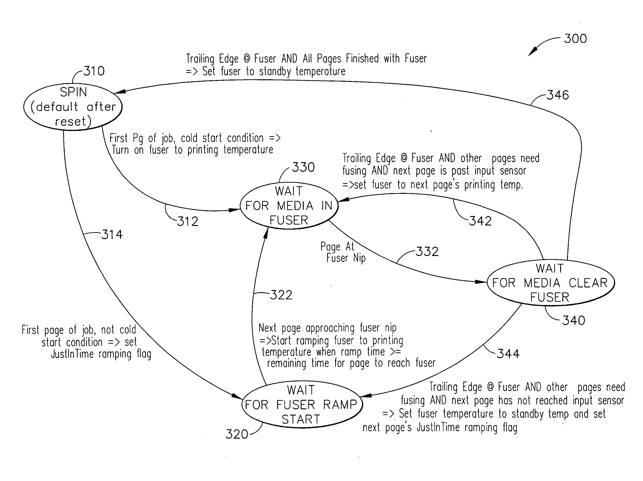
Benefits of technology

[0006] Accordingly, it is an advantage of the present invention to provide an electrophotographic (EP) printer, such as a laser printer, which uses a belt fuser that minimizes the warm-up time required in printing the first sheet of a new print job.
[0007] It is another advantage of the present invention to minimize the warm-up time of the belt fuser of an EP printer by applying a small amount of power to the fuser, to keep the fuser at an initial condition between the ambient machine (or room) temperature and the fixing temperature of the fuser of the EP printer.
[0008] It is yet another advantage of the present invention to provide an EP printer that minimizes the warm-up time of a belt fuser while also reducing voltage transients that can otherwise result in light flicker that might be created by current supplied to the fuser's heating element.
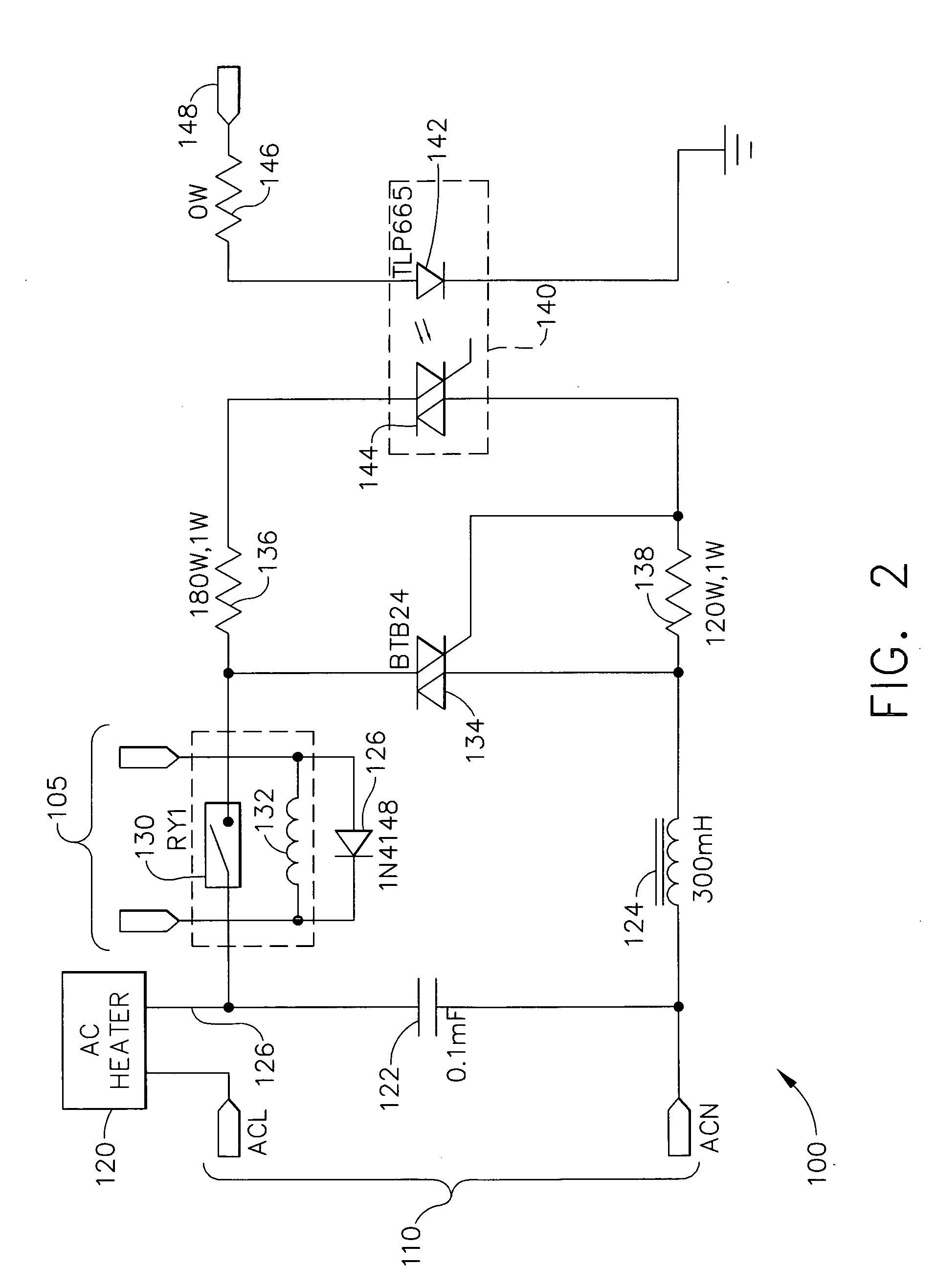
[0009] It is still another advantage of the present invention to reduce the warm-up time of the belt fuser of an EP printer while also reducing voltage and current transients by use of several possible control modes, including integer half-cycle control, or percent duty cycle control using a phase-controlled AC power circuit.
[0010] It is a further advantage of the present invention to provide an EP printer that minimizes the warm-up time of a fuser apparatus by use of a PID controller that operates in more than one control mode, including standby, ramping, and printing control modes.
[0011] It is yet a further advantage of the present invention to provide an EP printer that minimizes the warm-up time of a fuser apparatus by use of a PID controller that operates in more than one control mode, including standby, ramping, and printing control modes, and in which the PID control parameters exhibit different numeric gain values for some of the different control modes.

Problems solved by technology

Because of improvements in the time at which modern laser printers can generate an image, this finite warm up time has become the limiting factor in time to first print (TTFP).

Method used


Image

  • Method and apparatus for controlling temperature of a laser printer fuser with faster response time
  • Method and apparatus for controlling temperature of a laser printer fuser with faster response time
  • Method and apparatus for controlling temperature of a laser printer fuser with faster response time

Examples


first embodiment

[0068] Referring now to FIG. 7, a logic block diagram is provided generally designated by the reference numeral 400, which represents a temperature control algorithm usable with the fuser of the present invention. Starting at a block 410, the number of target “clicks” is received from a ramp table, or is a steady state value received from the controller. The term “clicks” refers to a numeric value, typically in the range of zero (0) through 255, for a control system having an 8-bit precision. The number of clicks would be zero (0) for a minimum value and 255 for a maximum value, representing the numeric integer values using this 8-bit precision. If this was translated into voltage levels, the zero (0) level could be represented by zero (0) volts DC, and the numeric click value 255 could be represented by +5 volts DC, for example.

[0069] The target clicks in the temperature control block diagram 400 represent the desired temperature that the fuser assembly 50 is to be set to. This num...

second embodiment

[0073] Referring now to FIG. 8, a logic block diagram is provided generally designated by the reference numeral 500, which represents a temperature control algorithm usable with the fuser of the present invention. Starting at a block 510, a reference temperature (in degrees C.) is received from the control system, which could be a steady state value received from the controller. This reference temperature represents the desired temperature that the fuser assembly 50 is to be set to, and will likely change its numeric value when the printer changes operating modes (e.g., from standby mode to printing mode).

[0074] The reference temperature 510 is directed down an arrow 512 to a difference function 520, in which the actual temperature of the fuser 570 (in degrees C.) is subtracted from the target temperature, resulting in a difference value, which is referred to as the “error” (also in units of degrees C.), at an arrow 522. This difference function 520 is a standard function used by ma...


PUM


Abstract

An improved laser printer is provided that keeps its fuser at a standby temperature that is somewhat raised above the ambient temperature, which allows the printer to operate more quickly (to begin printing the first page) when a print job arrives at the printer. The time needed to raise the fuser's temperature is minimized, so that other printer operations become the determining factor in the time to first print parameter. The electrical energy that energizes the fuser is provided in a form that prevents light flicker, by use of AC waveform phase control, or by use of integer half cycle control. The present invention uses closed-loop feedback control, and the type of controller is a PID controller.

Description

TECHNICAL FIELD [0001] The present invention relates generally to image forming equipment and is particularly directed to electrophotographic printers of the type which use heated fusers to fix toner onto print media. The invention is specifically disclosed as a laser printer that runs its belt fuser in a standby mode at a slightly raised temperature to operate more quickly when a print job arrives at the printer. The standby temperature of the fuser is low enough so that the movable components are not required to cycle to otherwise avoid thermal problems, but at the same time the standby temperature is raised to a temperature that allows the printer to begin printing the first page more quickly. If possible, it is preferred for the time required to raise the fuser temperature from the standby temperature to the fusing {or fixing} temperature to be short enough so that other printer operations become the determining factor in the time to first print parameter. (In past printers, the...

Claims


Application Information

Patent Timeline
IPC IPC(8): G03G15/20
CPCG03G15/205
Inventor BARTLEY, BRIAN KEITHHAMILTON, DOUGLAS CAMPBELLHARRIS, STEVEN JEFFREYSCHOEDINGER, KEVIN DEANSEARS, JOHNNY RAYSMITH, JERRY WAYNE
Owner LEXMARK INT INC
Why Eureka
Try Eureka