
Wave bearings in high performance applications

a technology of fluid film bearings and wave bearings, which is applied in the direction of bearings, shafts and bearings, rotary bearings, etc., can solve the problems of affecting the operation of such machinery, the prior art performance of bearings has not been shown in applications, and the operating conditions are beyond the capability of conventional ball and roller bearings, so as to improve the hydrodynamic effect, improve the stability, and improve the bearing load capacity.

Inactive Publication Date: 2006-04-13
DIMOFTE FLORIN
View PDF10 Cites 33 Cited by
  • Summary
  • Abstract
  • Description
  • Claims
  • Application Information

AI Technical Summary

Benefits of technology

[0021] The object of this invention is to provide bearings having a wave surface on the stationary bearing part while the rotating member has a plain configuration. In particular the present invention provides a pressurized gas journal bearing having a wave surface that adds an improved hydrodynamic effect when the shaft rotates, in conjunction with the pressure supplied externally. The shaft can rotate in both directions. The bearing load capacity, stiffness, and stability can be significantly improved as compared to either a pressurized plain bearing or an aerodynamic wave bearing. The present invention also provides a liquid lubricated journal wave bearing having a wave surface circumscribed on the diameter of the stationary part. The position of the waves and the lubricant supply ports position is optimized for the specific application. Any liquid, such as, for example, cryogenics, mineral and synthetic hydrocarbon oils, fuels, water, polyphenylethers (PPE), and perfluoropolyethers (PFPE), can be used. The bearing can run at any temperature at which the lubricant remains stable. Another object of the present invention is to provide a bidirectional double thrust wave bearing consisting of an axial disk located between a pair of thrust plates. In addition, the present invention provides a mono-directional singular thrust wave bearing consisting of an axial disk that faces a thrust plate. Either the disk or the thrust plate rotates. The stationary part of this bearing (either the thrust plate or the disk) has a wave surface incorporated into its active face. The interaction of the stationary wave surface and the plain running surface generates hydrodynamic pressures that allow the bearing to carry thrust loads. These thrust wave bearings can be lubricated with any gas or liquid and can run at any temperature (assuming lubricant stability). Finally, this invention provides wave bearings with an elastic stationary part. The elastic part has a wave surface that can be distorted to adapt the bearing performance to the applied loads and speeds. The distortions are made by actuators (as an “Active / Passive Control Fluid Film Bearing”) or by the hydrodynamic pressures between the stationary and rotating parts (as a “Smart Bearing”).

Problems solved by technology

Current standard journal bearings suffer from instabilities that can severely hinder operation of such machinery.
Such bearings as described in the prior art have not been shown to perform in applications where high temperatures in addition to high speed may be encountered.
Such operating conditions are beyond the capability of conventional ball and roller bearings.
Under even less severe conditions, ball and roller bearings become unreliable, with reduced life cycle, increased maintenance problems and costs, and increased safety concerns.
Conventional circular journal bearings are disadvantaged in high performance applications due to tendencies to promote shaft instabilities at high speeds and low load conditions.
The plain journal bearing has the highest load capacity, but shafts supported in it are subject to instabilities known as fractional frequency, whirl which can lead to failures.
The occurrence of fractional frequency whirl makes journal plain bearings unsuitable for lightly loaded, high speed applications.
Non-circular types of journal bearings can provide stable shaft operation and their use is obligatory in applications where “shaft whirl” is a problem.

Method used


Image

  • Wave bearings in high performance applications
  • Wave bearings in high performance applications
  • Wave bearings in high performance applications

Examples


Embodiment Construction

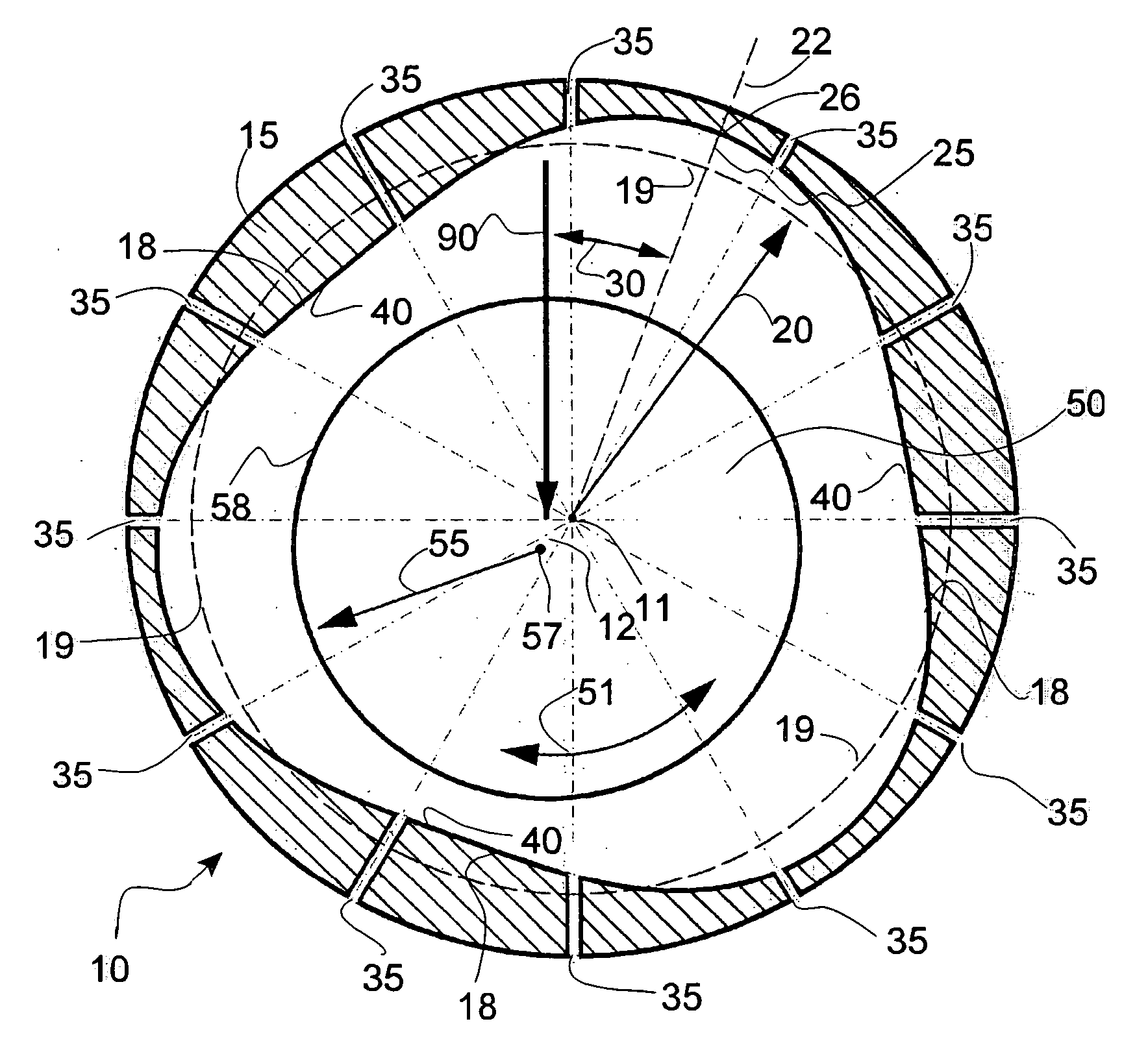
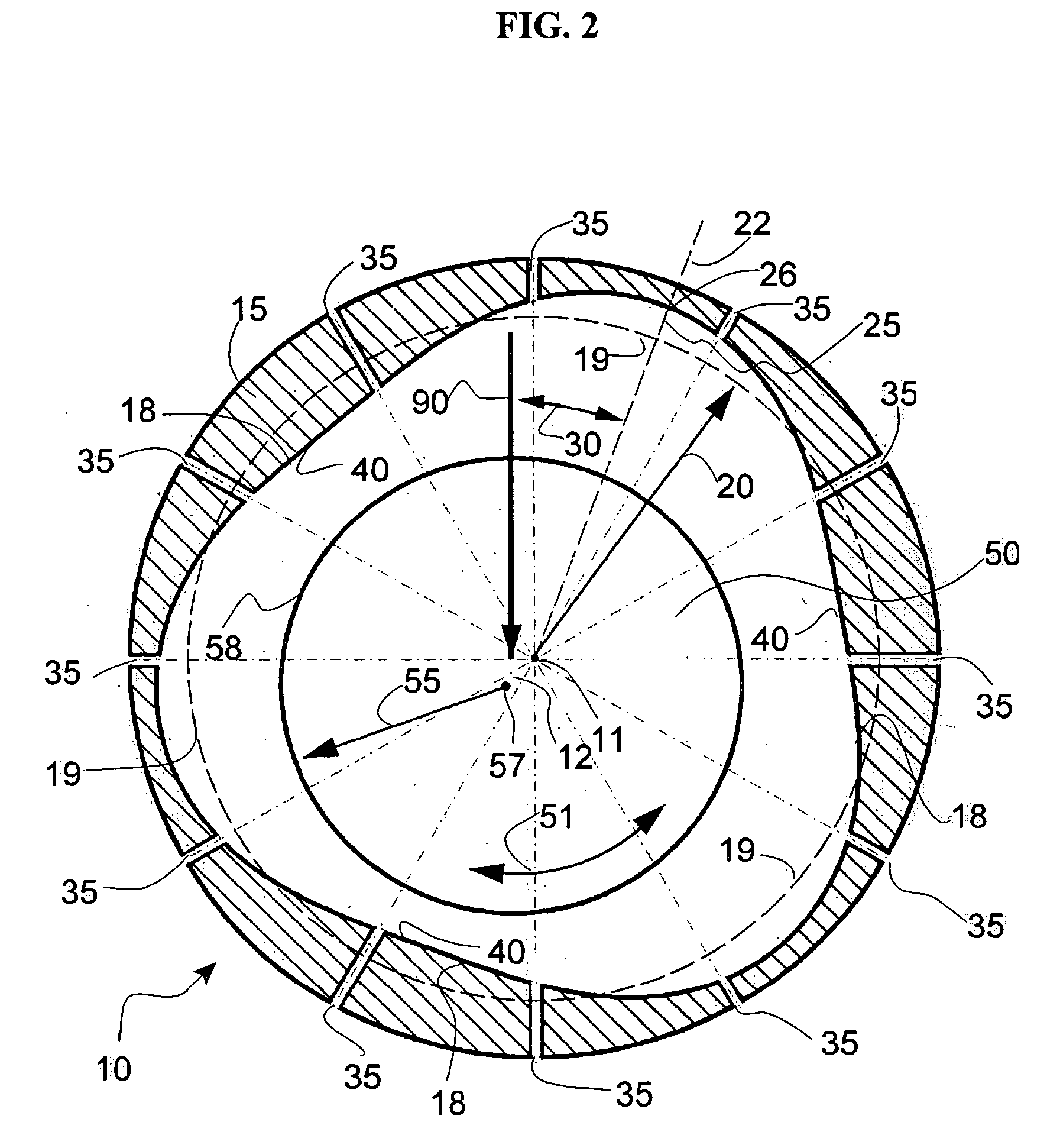
[0039] A pressurized gas journal wave bearing 10 according to the present invention is illustrated in FIG. 2. The journal bearing 10 supports a rotating shaft 50. A vertical load 90 is applied to the shaft 50.

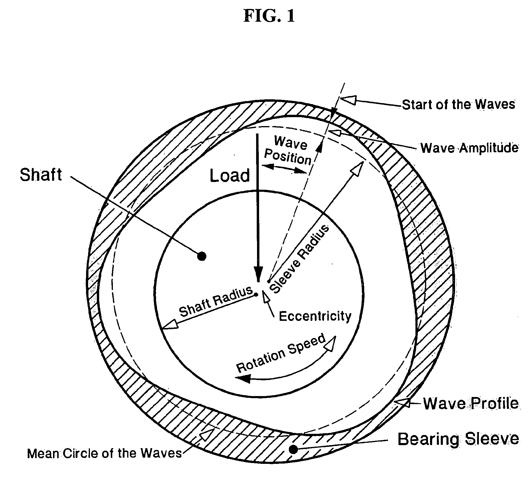
[0040] The bearing sleeve 15 has a wave surface 18 circumscribed on its inner diameter. If the shaft is stationary and the sleeve is rotating, the wave profile is circumscribed on the shaft diameter (not illustrated). The profile of the wave surface 18 shows a “mean circle”19. The radius 20 of the mean circle 19 is also the radius of the bearing sleeve. The wave surface has a starting point 22. The wave has an amplitude 25 which is the distance from the mean circle 19 to the maximum outside point of the wave 26. The position of the wave relative to the applied load direction 90 is defined by the wave position angle 30. The wave surface has a plurality of waves (three are illustrated here). The wave surface 18 is made either through a manufacturing process (such as grinding, la...


PUM


Abstract

The present disclosure concerns the application of the “Wave Bearing Concept” to journal and thrust fluid film bearings to increase performance and reliability. The wave surface is present on whichever member is stationary or non-rotating. Some applications are: pressurized gas journal wave bearings for increased load capacity and dynamic stability; journal wave bearings with liquid lubricants for extreme load capacity and excellent thermal and dynamic stability under any load; thrust wave bearings for axial positioning and axial loads; journal bearings with an elastic wave sleeve that can be activated via actuators (“active / passive control fluid film bearing”) or may change by itself (“smart bearings”) to adapt the bearing performance to the applied bearing load and speed. Journal and thrust bearings incorporating the present invention are appropriate for either mono-directional or bi-directional rotation.

Description

REFERENCES [0001] 1. Dimofte, F., “Wave Journal Bearing with Compressible Lubricant; Part I: The Wave Bearing Concept and a Comparison to the Plain Circular Bearing,” STLE Tribology Trans. Vol. 38, 1, pp.153-160, (1995). [0002] U.S. Patent Documents: 5,593,230Jan. 14, 1997Tempest, Michael, C., and Dimofte, Florin6,024,493Feb. 15, 2000Tempest, Michael, C., and Dimofte, Florin6,428,211Aug. 06, 2002Murabe, et al.6,402,385Jun. 11, 2002Hayakawa, et al.[0003] Statement of Federal Sponsored Research / Development: [0004] Federal founds were use in certain testing of the wave bearings. BACKGROUND OF THE INVENTION [0005] 1. Field of the Invention [0006] The present invention concerns journal and thrust fluid film bearings which include a wave surface to optimize load capacity, thermal stability, and dynamic behavior for varying operating conditions. [0007] 2. Description of Related Art [0008] High speed, high performance machines need stable, low friction bearings in order to operate smoothly...

Claims


Application Information

Patent Timeline
Patent Type & Authority Applications(United States)
IPC IPC(8): F16C32/06
CPCF16C17/02F16C17/04F16C32/0685F16C32/0692F16C33/1075F16C17/028F16C17/047
Inventor DIMOFTE, FLORIN
Owner DIMOFTE FLORIN
Learn More