
Methods and systems achieving print uniformity using reduced memory or computational requirements

a technology of applied in the field of image streak compensation, can solve the problems of image non-uniformity, photoreceptor scratches, and long-standing difficulties such as achieve the effect of less memory or computational requirements, less streaks, and less nois

Active Publication Date: 2006-04-13
XEROX CORP
View PDF9 Cites 58 Cited by
  • Summary
  • Abstract
  • Description
  • Claims
  • Application Information

AI Technical Summary

Benefits of technology

[0014] The present invention provides methods and systems that achieve print uniformity (i.e., streak compensation) using less memory or computational requirements to minimize the effects of streaks, printer noise and measurement noise.

Problems solved by technology

Image non-uniformity has long been a difficult problem for most digital marking processes.
They are typically caused by the undesirable non-uniform response of some components in a marking engine.
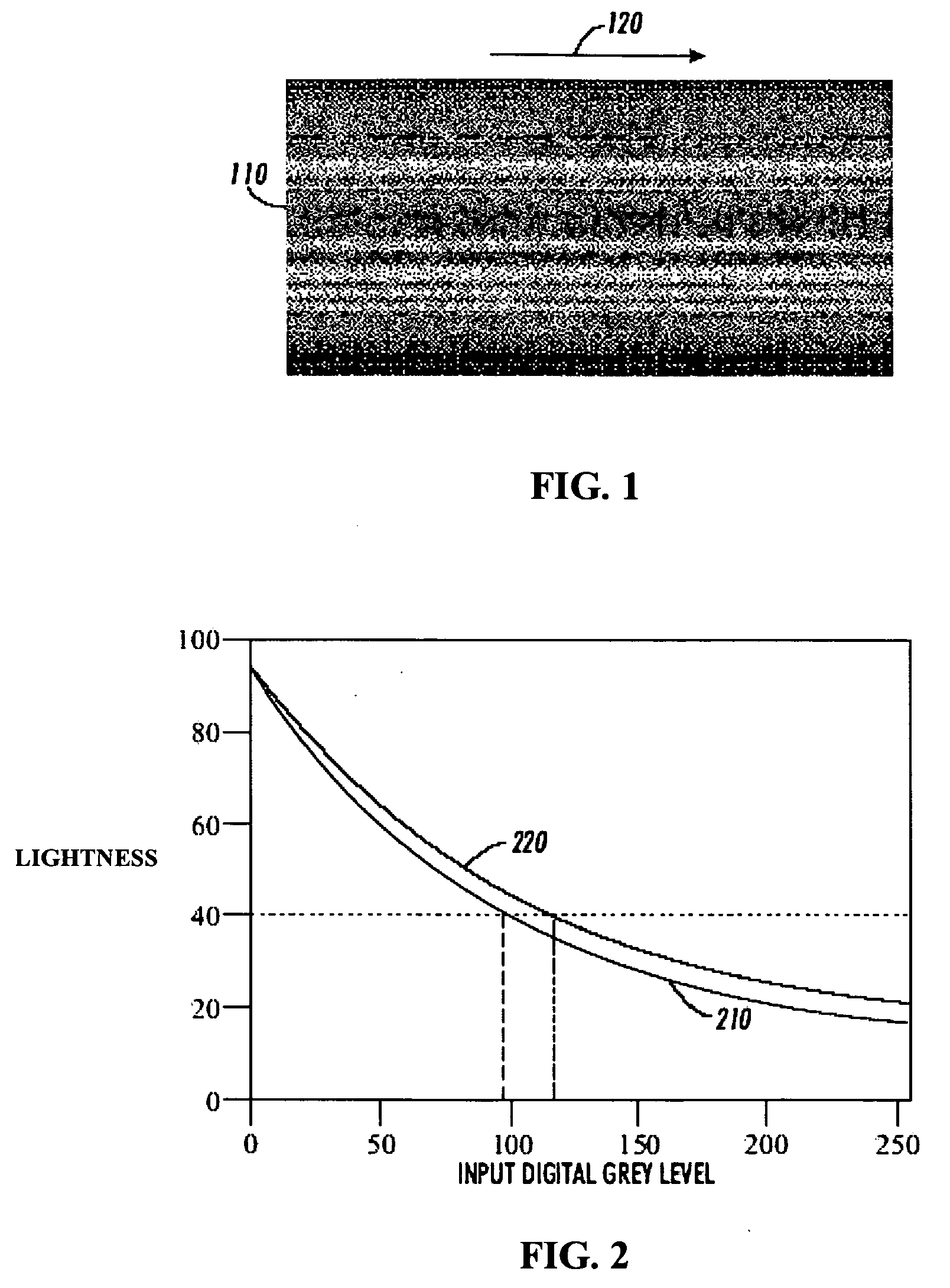
Defects in the subsystems of a xerographic printer, an inkjet printer, or similar image forming system may give rise to visible streaks in a printed image.
For example, photoreceptor scratches, contamination of the charger wire, non-uniform LED imager and Raster Output Scanner (ROS) spot size variations are examples of subsystem problems giving rise to rendered image streaking in a xerographic marking engine.
As a result, manufacturing and maintenance costs increase dramatically in order to cope with more stringent image quality requirements.
Such precision manufacturing, however, will often prove to be cost prohibitive.
Prior image processing solutions, however, presented fundamental concepts of streak compensation by providing detailed measurement and iteration methods, but did not develop details for an optimal method of selecting a set of TRCs that is practical and cost effective for common printing image path architectures.
This large beam, however, does not provide the resolution for the toner area coverage sensor to be useful as a sensor for the narrow streaks that may occur for poorly performing subsystems.

Method used


Image

  • Methods and systems achieving print uniformity using reduced memory or computational requirements
  • Methods and systems achieving print uniformity using reduced memory or computational requirements
  • Methods and systems achieving print uniformity using reduced memory or computational requirements

Examples


Embodiment Construction

[0052] Using methods of the present invention the number of spatial RCs required for streak compensation are reduced, yet real-time implementation of streak compensation becomes much simpler and more cost-effective. Also, the present invention can achieve better uniformity across pixel columns within a marking engine and across multiple marking engines, and can converge faster than previous spatial RC methods. The compensation techniques described herein can be applied to both color and monochrome image forming devices.

[0053] As used herein, the term “printed gray level” in reference to a print indicates an amount of reflectance due to an amount of coverage of material between zero and 100% for the allowable range on the printed surface, although in general this material may be colored any desired color. The printed gray level may be represented as a percentage, or some optical unit (e.g., lightness).

[0054] An “input gray level” is typically a digital value represented as an integ...


PUM


Abstract

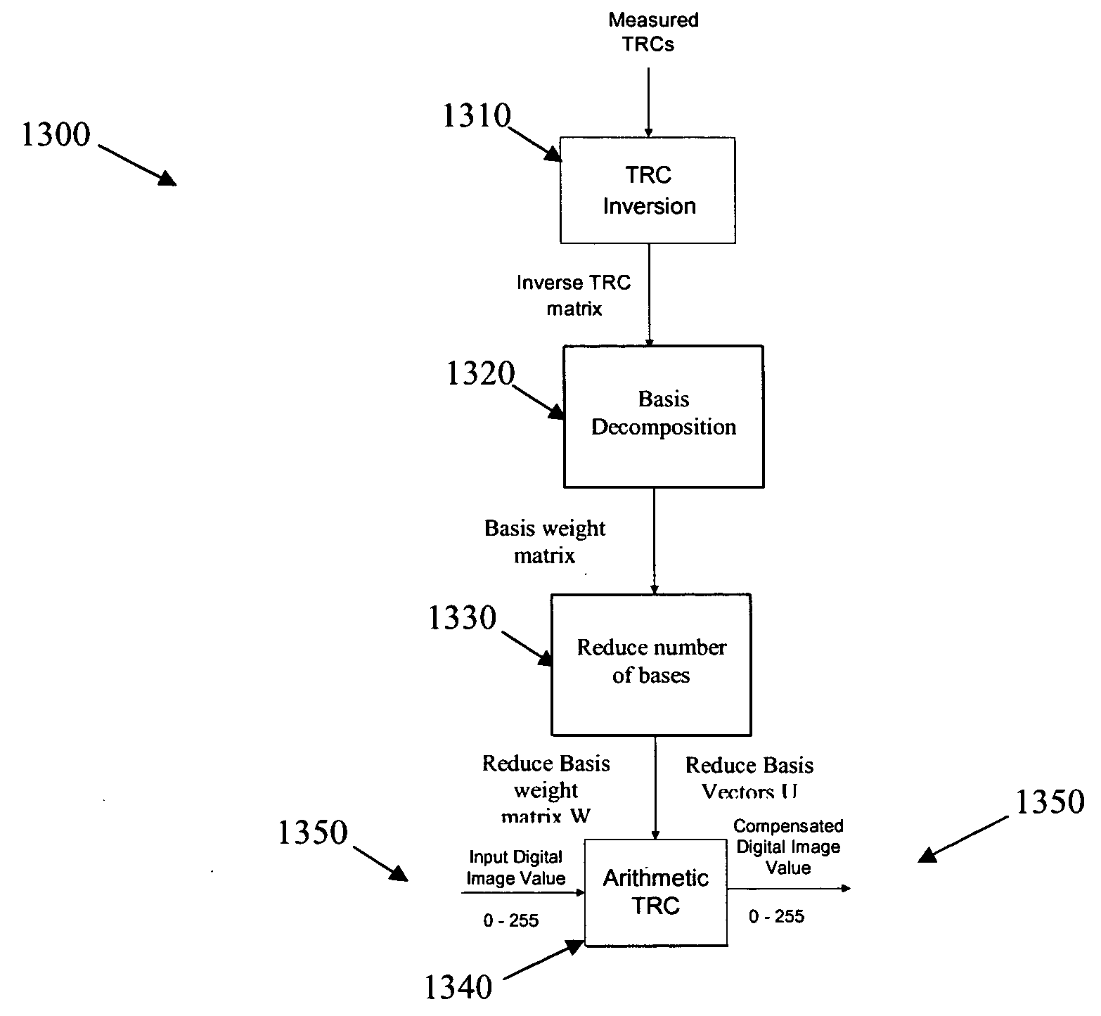
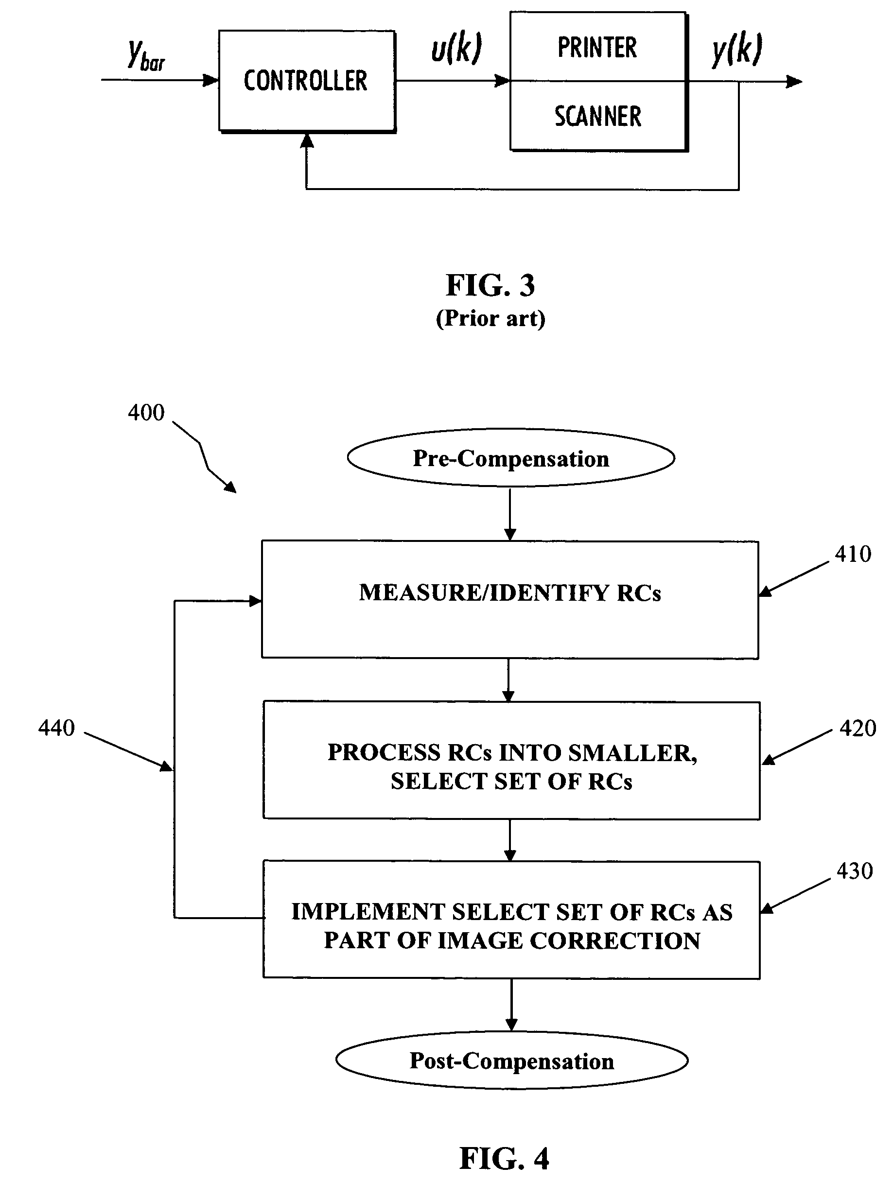
Engine response curves (RCs) can be used for streak compensation for printed documents. A feedback control paradigm can be included to effect RC compensation. Singular Value Decomposition (SVD) can be used to represent each RC in the collection of spatial RC data as a linear combination of basis vectors. RCs are approximated by selecting the first few basis vectors, the approximation aiding in noise rejection and reducing computation in the controller by reducing dimensionality of the RC data from gray levels to the number of SVD bases selected. An optimal subset of RCs is selectable from the set of approximated RCs by clustering the SVD weights, the clustered SVD weights producing TRCs that span all engine response RCs generated by a printer. Compensation RCs are constructible using reduced number of bases and clustered SVD weights

Description

FIELD OF THE INVENTION [0001] The present invention is generally related to image streak compensation in printed material. More particularly, the present invention is related to methods and systems achieving print uniformity using reduced memory or computational requirements while minimizing the effects of printer noise and measurement noise. BACKGROUND [0002] Image non-uniformity has long been a difficult problem for most digital marking processes. Streaks are one-dimensional image defects that generally run parallel to the process direction in a printed image. They are typically caused by the undesirable non-uniform response of some components in a marking engine. Defects in the subsystems of a xerographic printer, an inkjet printer, or similar image forming system may give rise to visible streaks in a printed image. For example, photoreceptor scratches, contamination of the charger wire, non-uniform LED imager and Raster Output Scanner (ROS) spot size variations are examples of s...

Claims


Application Information

Patent Timeline
IPC IPC(8): H04N1/46
CPCH04N1/407H04N1/4097
Inventor VIASSOLO, DANIEL E.ZOLTNER, SUSAN J.MIZES, HOWARD A.LOCE, ROBERT P.
Owner XEROX CORP
Learn More