
Inverse tracking over two different clock domains

a clock domain and clock domain technology, applied in the field of video decoders, can solve the problems of only realizing gains, and achieve the effect of greatly enhancing the accuracy of brightness (amplitude) and color (phase) information, and substantially reducing the noise in the system

Inactive Publication Date: 2006-04-13
CIRRUS LOGIC INC
View PDF7 Cites 6 Cited by
  • Summary
  • Abstract
  • Description
  • Claims
  • Application Information

AI Technical Summary

Benefits of technology

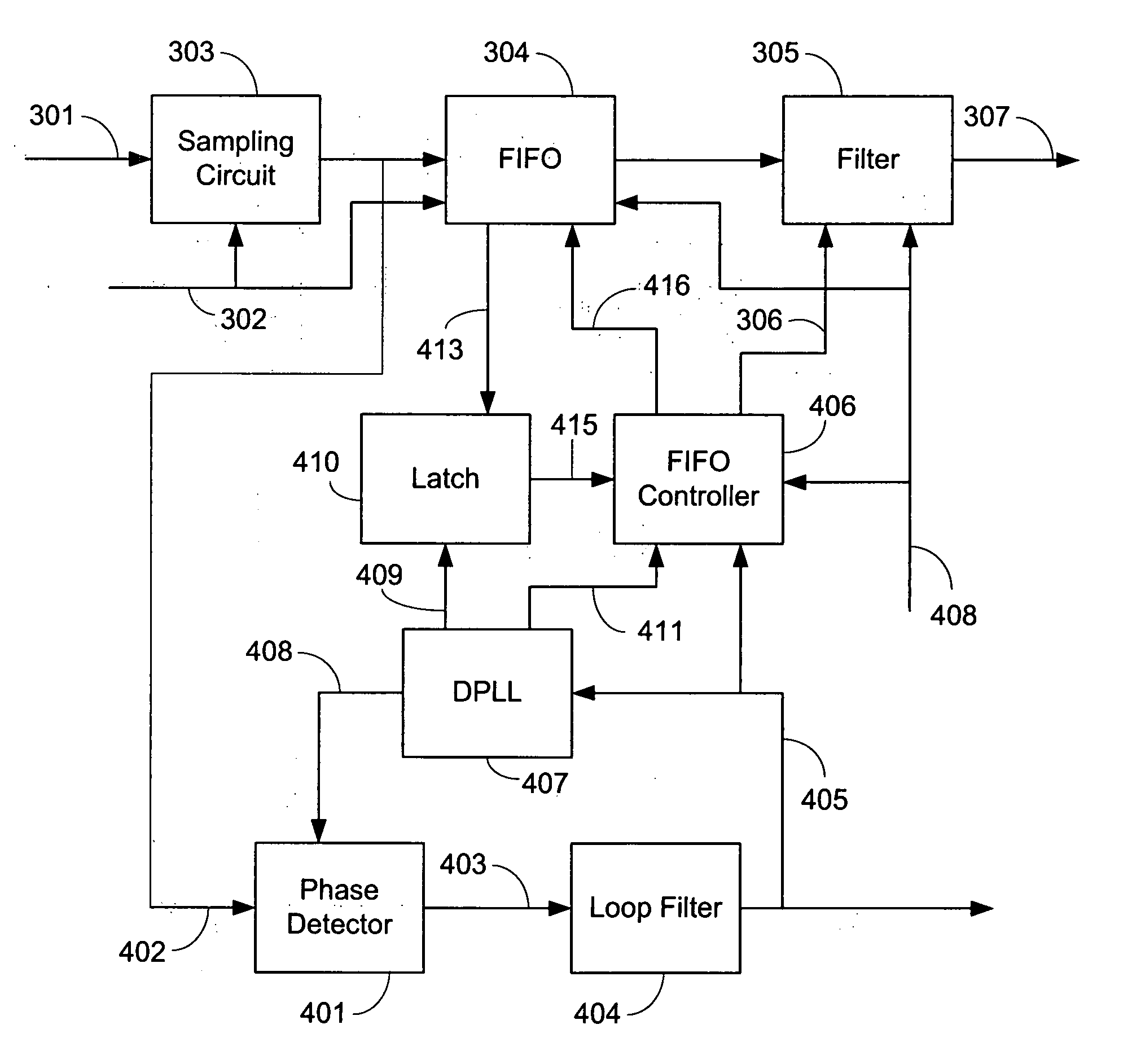
[0007] The present invention is directed to a video decoder that addresses the foregoing problems. The present invention differs from the prior art in that the source clock is generated entirely in the digital domain, which has the following advantages. By creating a virtual version of the source clock in a numeric oscillator, the amount of noise in the system is substantially reduced. Furthermore, by transferring the digitized video signal, sampled with an asynchronous crystal clock, into the source clock domain, the accuracy of the brightness (amplitude) and color (phase) information can be greatly enhanced.

Problems solved by technology

However, these gains can only be realized if the time base of the sampled composite video signal is converted from the sample clock back to the video source clock so that brightness and color information contained in the video signal can be more accurately recovered.

Method used


Image

  • Inverse tracking over two different clock domains
  • Inverse tracking over two different clock domains
  • Inverse tracking over two different clock domains

Examples


Embodiment Construction

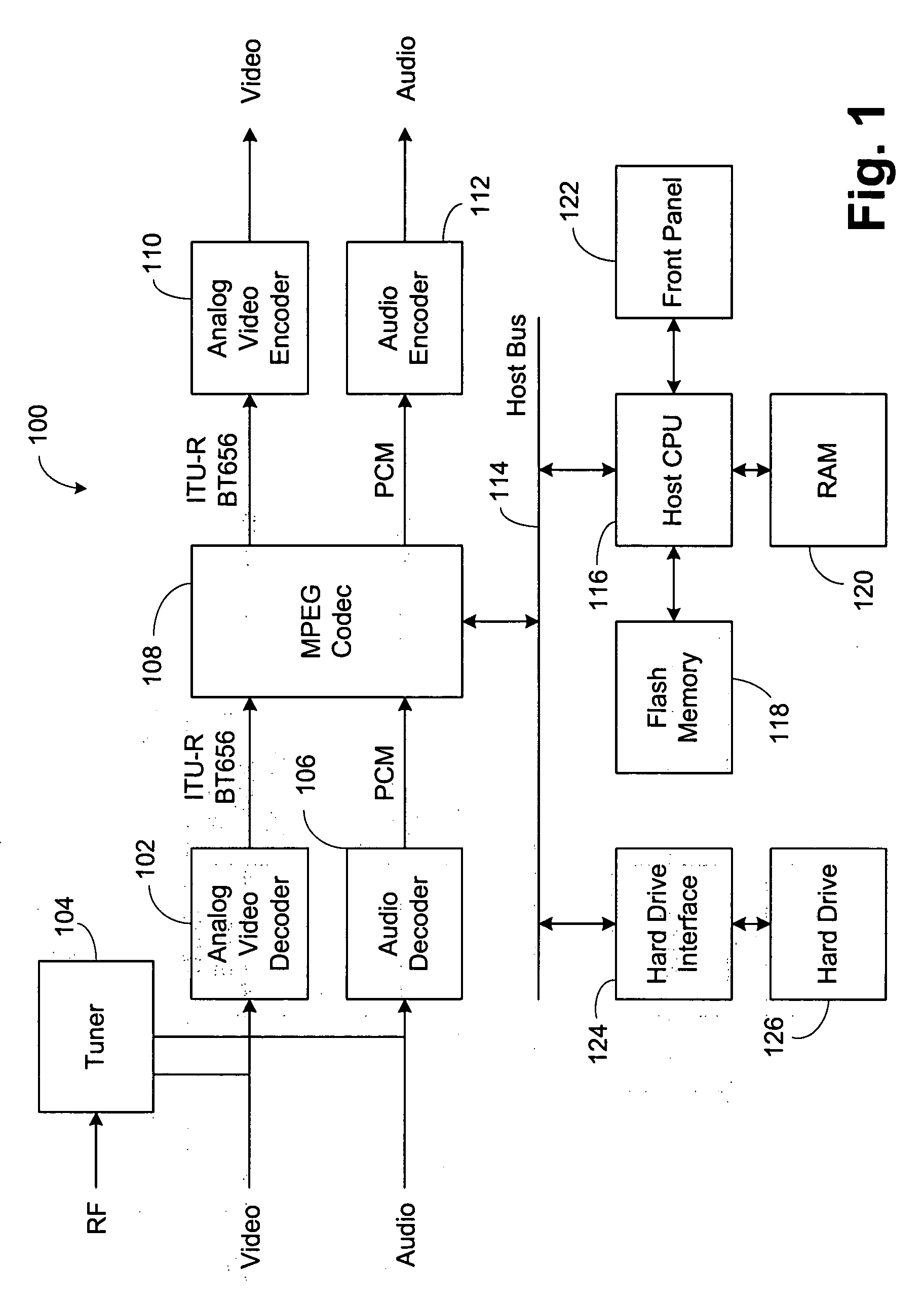
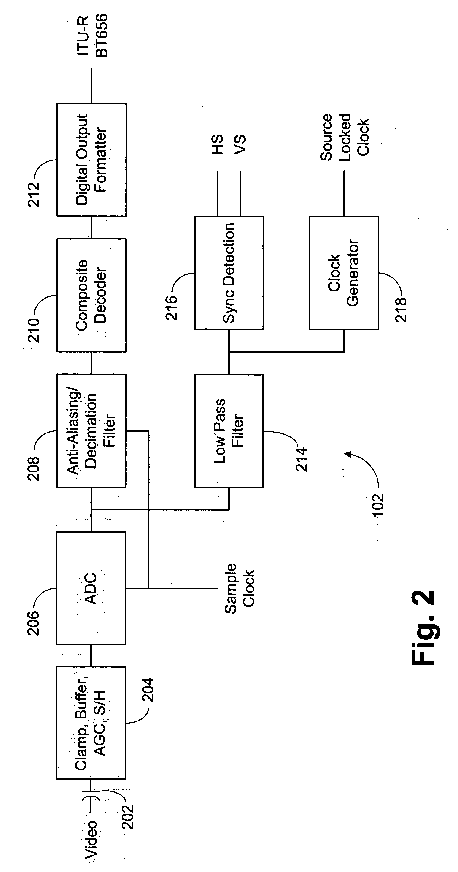
[0012] Referring now to FIG. 1, an exemplary personal video recorder (PVR) 100 is shown. This is an exemplary use of analog video decoder 102, and it is understood that the analog video decoder can be used in multiple applications including digital televisions, LCD TVs, DVD recorders, video capture situations, and the like. A radio frequency (RF) or broadcast signal is provided to a tuner 104. The tuner 104 provides both video and audio outputs. The video output from the tuner 104 or a video signal from an external connection is provided to analog video decoder 102. The audio signal from the tuner 104 or an external audio signal is provided to an audio decoder 106. The output from the analog video decoder 102 is preferably an ITU-R BT 656 format digital signal, which is either an eight or ten bit signal. This digital signal from video decoder 102 is provided to an MPEG (Moving Pictures Expert Group) codec 108 to perform video compression in the digital domain. Similarly, the audio d...


PUM


Abstract

A video decoder in which the video source clock is generated entirely in the digital domain is disclosed herein. By creating a virtual version of the source clock in a numeric oscillator, the amount of noise in the system is substantially reduced. Furthermore, by transferring the digitized video signal, sampled with an asynchronous crystal clock, into the source clock domain, the accuracy of the brightness (amplitude) and color (phase) information can be greatly enhanced.

Description

BACKGROUND OF THE INVENTION [0001] 1. Field of the Invention [0002] The invention generally relates to video decoders and more specifically to systems and techniques for correcting the time base of a sampled composite video signal wherein the sample clock and video source clock are asynchronous. [0003] 2. Description of Related Art [0004] There is a large surge in the use of digital video devices today. Examples include: digital televisions, LCD (Liquid Crystal Display) TVs (televisions) and monitors, DVD (Digital Versitile Disc) recorders, personal video recorders, PC (Personal Computer) video cards, video capture and streaming applications, and video conferencing. In many cases, these units need to receive an analog video signal, which may be one of the composite signals, such as NTSC (National Television Standards Committee), PAL (Phase Alternating Line), SECAM (Sequential Couleur Avec Mémoire), S-video, component video, or RGB (Red, Green, Blue). It is then desirable to produce ...

Claims


Application Information

Patent Timeline
IPC IPC(8): H04N11/00
CPCH03L7/06H03L7/0991H03L2207/50H04L7/0331H04N5/126H04L7/005
Inventor GUDMUNDSON, DANIELMELANSON, JOHN L.SINGH, RAHULCHOWDHURY, AHSAN HABIB
Owner CIRRUS LOGIC INC
Learn More