
Synchronous image-switching device and method thereof

a technology of image switching and synchronous image, which is applied in the direction of instruments, conversion with storage device usage, and conversion involving interpolation processes. it can solve the problems of user inconvenience, higher power consumption, and inability to determine if any resolution adjustment is required. it achieves the effect of low power consumption

Inactive Publication Date: 2006-04-13
BEYOND INNOVATION TECH
View PDF21 Cites 9 Cited by
  • Summary
  • Abstract
  • Description
  • Claims
  • Application Information

AI Technical Summary

Benefits of technology

[0007] Accordingly, one object of the present invention is to provide a synchronous image-switching device capable of switching images synchronously with low power consumption.
[0011] In the present invention, the clocking signal of the image source and the clocking signal of the image destination are not necessarily related and a lower operating frequency is used. Accordingly, synchronous switching can be carried out at a relatively low power consumption.

Problems solved by technology

Therefore, the user could not determine if any adjustment in the resolution is required before display.
Hence, the power consumption is higher and may bring users some inconvenience.

Method used


Image

  • Synchronous image-switching device and method thereof
  • Synchronous image-switching device and method thereof
  • Synchronous image-switching device and method thereof

Examples


Embodiment Construction

[0021] Reference will now be made in detail to the present embodiments of the invention, examples of which are illustrated in the accompanying drawings. Wherever possible, the same reference numbers are used in the drawings and the description to refer to the same or like parts.

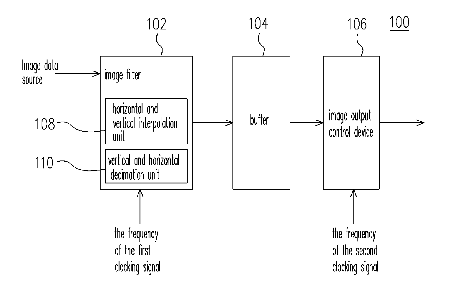
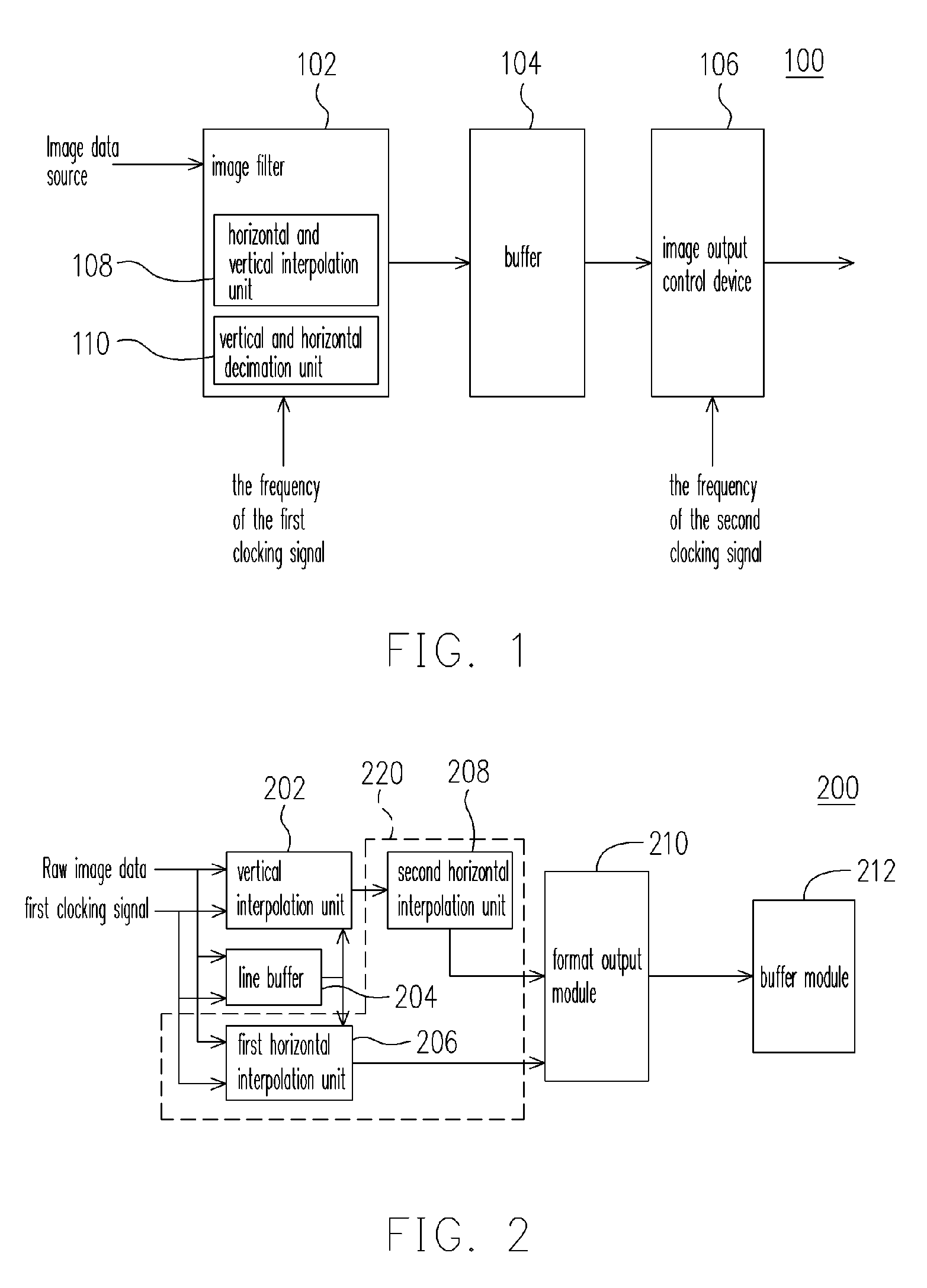
[0022] For a clear understanding of the technique provided by the present invention, please refer to FIGS. 1 and 4. FIG. 1 is a block diagram showing a synchronous image-switching device according to one embodiment of the present invention. FIG. 4 is a block diagram showing a synchronous image-switching method according to one embodiment of the present invention. The synchronous image-switching device 100 comprises an image filter 102, a buffer 104 and an image output control device 106. The image filter 102 is electrically coupled to the input terminal of the buffer 104 and the output terminal of the buffer is electrically coupled to the image output control device 106.

[0023] As shown in FIG. 1, a first cl...


PUM


Abstract

A synchronous image-switching device and switching method thereof are provided. The synchronous image-switching device comprises an image filter for generating target image data according to the frequency of a first clocking signal, a buffer for holding the target image and an image output control device for outputting the target image according to the frequency of a second clocking signal. Because the synchronous switching device of the present invention allows the clocking frequency of the source image to be different from that of the target image, images can be switched synchronously and power consumption of the switching operation can be reduced.

Description

CROSS-REFERENCE TO RELATED APPLICATION [0001] This application claims the priority benefit of Taiwan application serial no. 93130842, filed on Oct. 12, 2004. All disclosure of the Taiwan application is incorporated herein by reference. BACKGROUND OF THE INVENTION [0002] 1. Field of the Invention [0003] The present invention relates to an image-switching device. More particularly, the present invention relates to a synchronous image-switching device. [0004] 2. Description of the Related Art [0005] Due to the rapid development of display devices, electronic screens are applied to various electronic products including digital cameras, liquid crystal display (LCD) televisions and liquid crystal display (LCD) monitors. In general, the displayed image and the image source have different resolutions so that the user would not know if the resolution of the next image data matches the pre-set resolution in the current system. Therefore, the user could not determine if any adjustment in the r...

Claims


Application Information

Patent Timeline
IPC IPC(8): G09G5/00G09G3/20H04N7/01
CPCG09G3/2096G09G2340/0414G09G2340/0421G09G2360/02H04N7/0105H04N7/0135
Inventor SHEN, CHUNG-LI
Owner BEYOND INNOVATION TECH
Learn More