Control circuit for charging/discharging of secondary cell and a sensor node
a control circuit and sensor node technology, applied in safety/protection circuits, battery overheating protection, lighting and heating apparatus, etc., can solve the problems of reducing affecting the operation of the sensor net system, and affecting the safety of the battery, so as to reduce the mounting surface area, reduce the power consumption, and prolong the battery life.
- Summary
- Abstract
- Description
- Claims
- Application Information
AI Technical Summary
Benefits of technology
Problems solved by technology
Method used
Image

Examples
embodiment 1
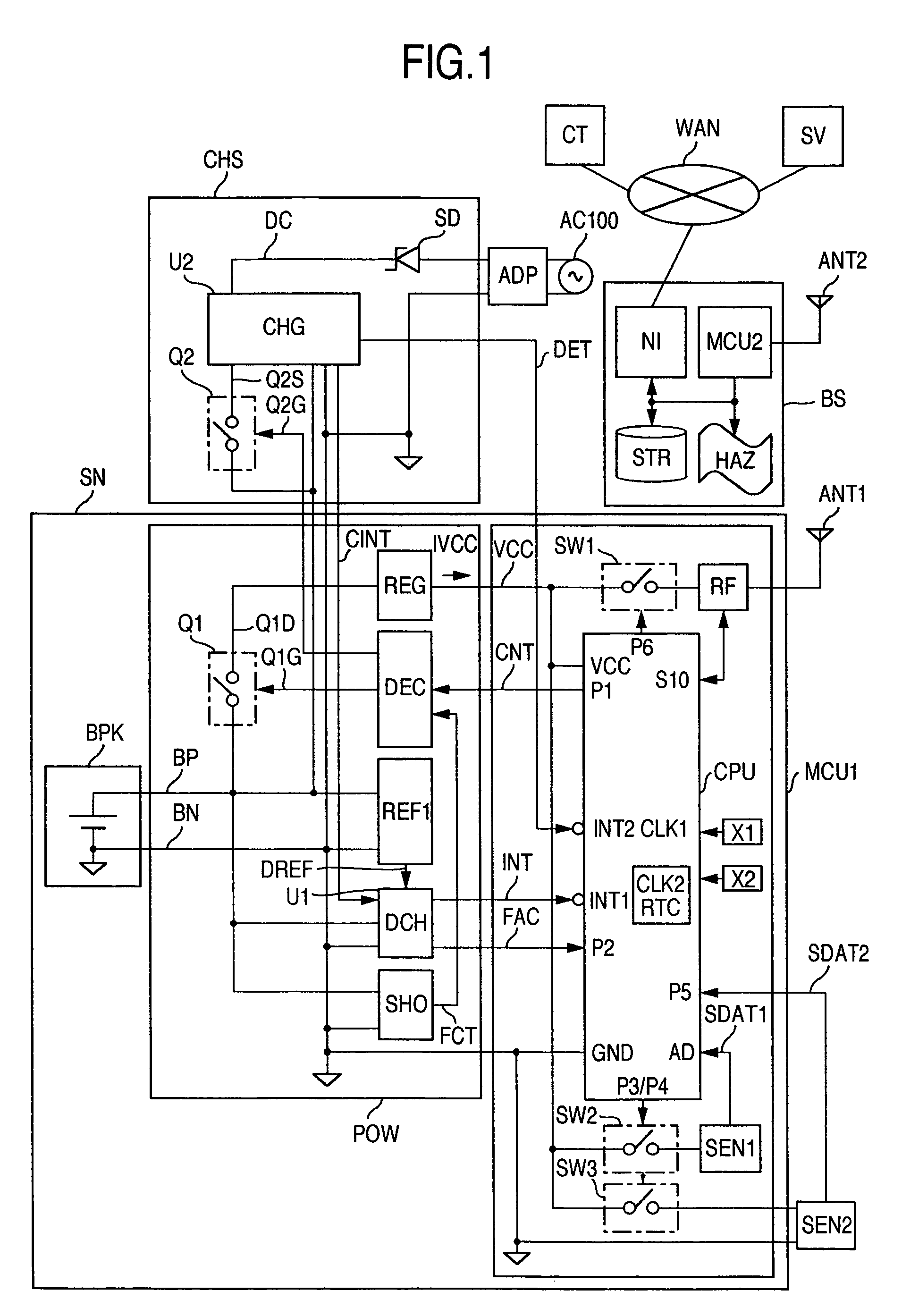
[0035]FIG. 1 shows a block diagram of an arrangement of a secondary-battery charge / discharge control circuit and a sensor node in accordance with a first embodiment of the present invention. A sensor net system includes a sensor node SN, a charger CHS, an AC adaptor ADP, a communication network WAN, a radio base station BS, a server SV, and a control center CT connected via the communication network WAN. The sensor node SN informs the radio base station BS of sensed data SDAT1 and SDAT2 by radio communication, the sensed result is displayed on a display device HAZ and stored in a storage STR. And a network interface circuit NI also stores the sensed result in the server SV via the communication network WAN. The control center CT connected to the communication network WAN performs centralized control of the sensor node SN. When a secondary battery BPK mounted in the sensor node SN is required to be charged, the AC adaptor ADP and the charger CHS are connected to the sensor node SN to...
embodiment 2
[0084]FIG. 10 shows a configuration when the number of signal lines for connection between the charger CHS and the sensor node SN is minimized. The configuration having a minimized number of signal lines for connection between the charger CHS and the sensor node SN can reduce the size of a connector to be mounted to the sensor node SN and thus the size of the sensor node SN can also be reduced. When compared with the first embodiment of FIG. 1, the charge stop voltage detection signal CINT and the charge stop switch control signal Q2G of the charge stop switch Q2 are omitted in the present configuration.
[0085] In the first embodiment of FIG. 1, the charge control after the charge stop voltage detection signal CINT is set is carried out under control of the micro controller CPU, and thus there are present signal lines for the charge stop voltage detection signal CINT and the charge stop switch control signal Q2G. In the second embodiment, on the other hand, all the operations until ...
embodiment 3
[0087]FIG. 12 is a circuit diagram for explaining a configuration when two secondary batteries BPK1 and BPK2 are connected in parallel. The radio communications circuit RF and the sensors SEN1 and SEN2 in the sensor node SN may, in some cases, require relatively large currents. In this case, the secondary batteries are mounted in parallel to increase the current and capacity.
[0088] Negative terminals BN of the first and second secondary batteries BPK1 and BPK2 are commonly connected; whereas, positive terminals BP11 and BP12 of the first and second batteries BPK1 and BPK2 are connected to the charge / discharge control circuit POW respectively. The micro controller control circuit MCU1, the second sensor SEN2, and the antenna ANT1 in FIG. 12 have the same structures as those in FIG. 1; and explanation thereof is omitted in FIG. 12. The charge / discharge control circuit POW has a first discharge stop switch Q11, a second discharge stop switch Q12, the regulator REG, the voltage monitor...
PUM
 Abstract
Description
Claims
Application Information
 - R&D
- Intellectual Property
- Life Sciences
- Materials
- Tech Scout
- Unparalleled Data Quality
- Higher Quality Content
- 60% Fewer Hallucinations
Browse by: Latest US Patents, China's latest patents, Technical Efficacy Thesaurus, Application Domain, Technology Topic, Popular Technical Reports.
© 2025 PatSnap. All rights reserved.Legal|Privacy policy|Modern Slavery Act Transparency Statement|Sitemap|About US| Contact US: help@patsnap.com