
System and method for providing sheets to an inserter system using a rotary cutter

a technology of inserter system and rotary cutter, which is applied in the field of inserter input system, can solve the problems of rotary cutter requiring a significant amount of time to decelerate, affecting the speed of rotary cutter, and affecting the efficiency of rotary cutter, so as to achieve the effect of small floor space and without significant lengthening of buffer modules

Inactive Publication Date: 2006-04-13
PITNEY BOWES INC
View PDF14 Cites 1 Cited by
  • Summary
  • Abstract
  • Description
  • Claims
  • Application Information

AI Technical Summary

Benefits of technology

[0019] The present invention overcomes disadvantage of the prior art by obtaining performance characteristics of a rotary cutter without having to use unreliable refeed devices to accommodate sheets generated during a stopping condition. The invention also provides efficiency in that the preferred embodiment can handle the necessary number of sheets using relatively little floor space, and without significant lengthening of a buffer module.
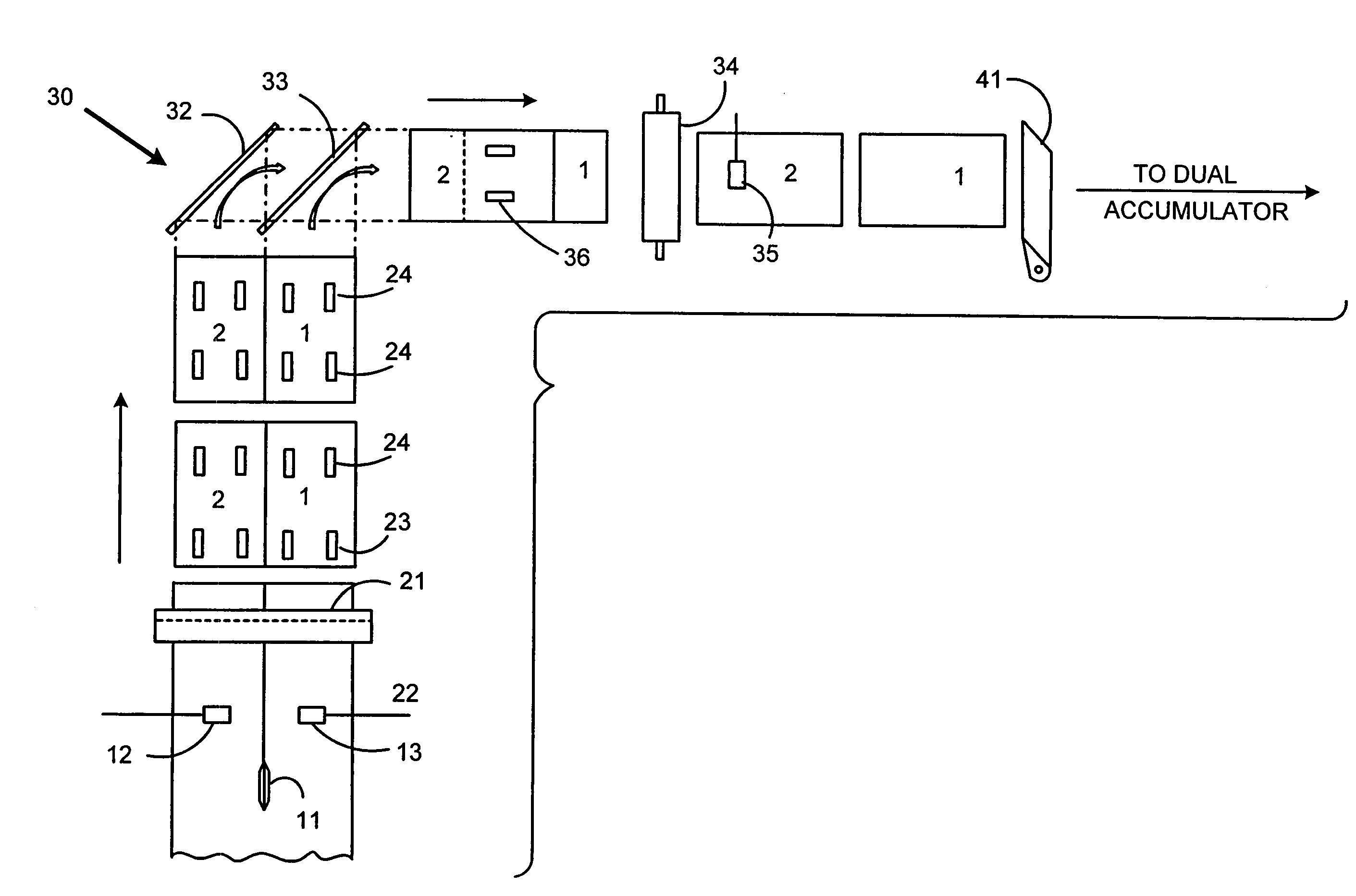
[0021] After the web is split along its length, a rotary web cutter cuts the web in a direction transverse to the travel direction. Thus, the web is cut into at least two side-by-side sheets. The rotary cutter is typically comprised of a rotating roller with a blade along its length. Downstream of the rotary cutter, a right angle turn mechanism receives each of the side-by-side sheets and reorients them by ninety degrees. Also, the sheets are changed from the side-by-side orientation to a serial and shingled arrangement. This serial shingled arrangement provides storage capacity for sheets over a shorter length.

Problems solved by technology

During high speed operation, the accelerations experienced by the web in the slack loop can be quite severe.
The inertia experienced by the web from the sudden starting and stopping may cause it to tear or become damaged.
However, a different disadvantage exists in that a rotary cutter requires a significant amount of time to decelerate when a downstream condition occurs that requires the system to stop.
A frequent limitation on speed of an inserter system is the ability of the system to handle all of the generated documents if the system is required to stop.
An input system may be capable of going very fast under non-stop operating conditions, but a problem arises during stopping if there isn't a means to handle all the sheets produced by the input system.
The work-in-progress problem is amplified when a rotary cutter is used.
Because of its greater inertia, a rotary cutter cannot be stopped as quickly as the guillotine style cutter.
Such additional capacity typically adds to the size and expense of the system.
Unfortunately, while solving one problem with rotary cutters, refeed devices cause another problem of their own.
Refeed devices have been found to be insufficiently reliable for consistent feeding of cut sheets in the input subsystem of a high-speed inserter.

Method used


Image

  • System and method for providing sheets to an inserter system using a rotary cutter
  • System and method for providing sheets to an inserter system using a rotary cutter
  • System and method for providing sheets to an inserter system using a rotary cutter

Examples


Embodiment Construction

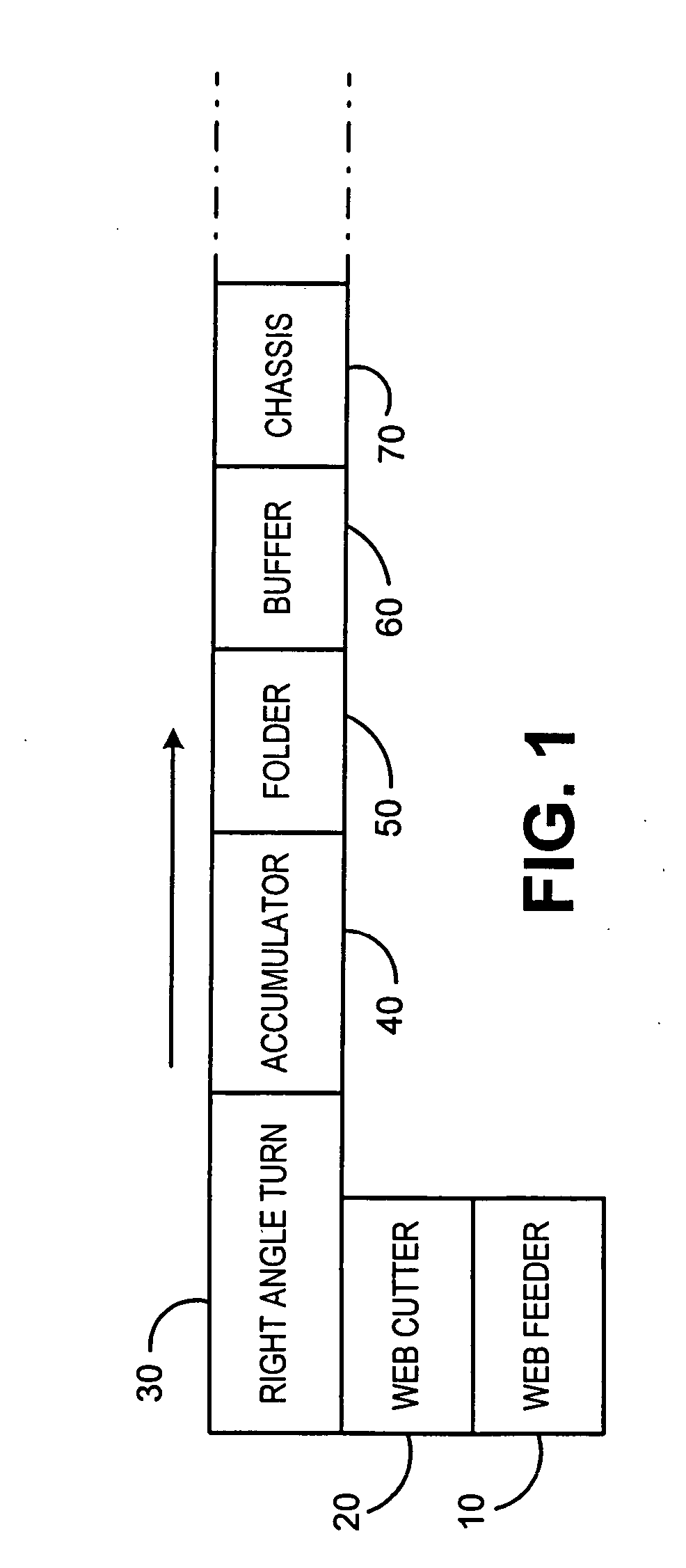
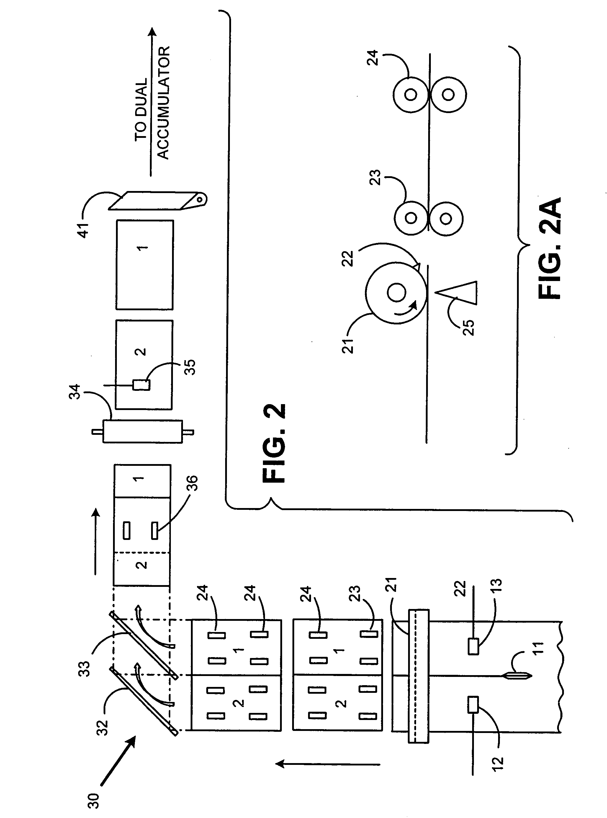
[0029] A preferred embodiment for implementing the present invention is depicted in FIG. 2. The components depicted in FIG. 2 may be associated with the general input stages depicted in FIG. 1, however it is not necessary that the particular components be part of any particular module, so long as they perform as described herein.

[0030] A web 100 is drawn into the inserter input subsystem. Methods for transporting the web are known and may include rollers, or tractors pulling on holes along a perforated strip at the edges of the web. The web 100 is split into two side-by-side portions by a cutting device 11. Cutting device 11 may be a stationary knife or a rotating cutting disc, or any other cutting device known in the art. While the embodiment in FIG. 2 shows the web being split into two portions, one skilled in the art will understand that a plurality of cutting devices 11 may be used to create more than two strands of web from the original one. Further, the processing steps descr...


PUM

PropertyMeasurementUnit
distanceaaaaaaaaaa
widthaaaaaaaaaa
constant transport velocityaaaaaaaaaa

Abstract

An inserter input system including a web feeder providing a web of printed material to be split by a web slitting knife along the web's direction of travel. The split web is then cut transverse to the direction of travel by a rotary cutter operating at a first velocity, resulting in side-by-side individual sheets. Downstream of the rotary cutter, a right angle turn mechanism receives each of the side-by-side sheets and reorients them by ninety degrees. Further the right angle turn reorients the sheets into a serial shingled arrangement. A high speed separation nip pulls individual shingled sheets out from the shingled arrangement. The speed of the separation nip is such that a predetermined gap between the previously shingled sheets is formed. In a further preferred embodiment of the present invention, the speed of the rotary cutter and right angle turn mechanism are controlled to adjust a quantity of sheets that would be generated from displacement traveled due to inertia during a deceleration of the system to a stop.

Description

TECHNICAL FIELD [0001] The present invention relates to an inserter input system for generating sheets of printed material to be collated and inserted into envelopes. Such an inserter input system cuts and processes a continuous web of material into individual sheets. The individual sheets may then be processed into individual mail pieces. BACKGROUND OF THE INVENTION [0002] Inserter systems, such as those applicable for use with the present invention, are typically used by organizations such as banks, insurance companies and utility companies for producing a large volume of specific mailings where the contents of each mail item are directed to a particular addressee. Also, other organizations, such as direct mailers, use inserts for producing a large volume of generic mailings where the contents of each mail item are substantially identical for each addressee. Examples of such inserter systems are the 8 series, 9 series, and APS™ inserter systems available from Pitney Bowes Inc. of ...

Claims


Application Information

Patent Timeline
Patent Type & Authority Applications(United States)
IPC IPC(8): B26D7/06B07C5/34B26D1/143B26D1/24B26D1/62B26D3/00B26D5/20B26D9/00B43M3/04B65H35/02B65H35/04
CPCB26D1/1435B26D1/245B26D1/626B26D9/00B43M3/045B65H29/6609B65H35/02B65H35/04B65H2301/3423B65H2301/44514Y10T83/04Y10T83/0467Y10T83/2192Y10T83/6491
Inventor SUSSMEIER, JOHN W.MASOTTA, JOHN R.ROZENFELD, BORISWRIGHT, WILLIAM J.
Owner PITNEY BOWES INC
Learn More