
Audio coding device with fast algorithm for determining quantization step sizes based on psycho-acoustic model

Active Publication Date: 2006-04-06
FUJITSU LTD
View PDF6 Cites 88 Cited by
  • Summary
  • Abstract
  • Description
  • Claims
  • Application Information

AI Technical Summary

Benefits of technology

[0010] In view of the foregoing, it is an object of the present invention to provide an audio coding device that can quantize transform coefficients with a reduced amount of computation while considering the characteristics human auditory system.

Problems solved by technology

However, the existing methods for this calculation require a considerable amount of computation.
Because of a fair amount of time that it spends to reach the convergence of calculation, this technique is not the best for reduction of computational load.

Method used


Image

  • Audio coding device with fast algorithm for determining quantization step sizes based on psycho-acoustic model
  • Audio coding device with fast algorithm for determining quantization step sizes based on psycho-acoustic model
  • Audio coding device with fast algorithm for determining quantization step sizes based on psycho-acoustic model

Examples


Embodiment Construction

[0026] Preferred embodiments of the present invention will be described below with reference to the accompanying drawings, wherein like reference numerals refer to like elements throughout.

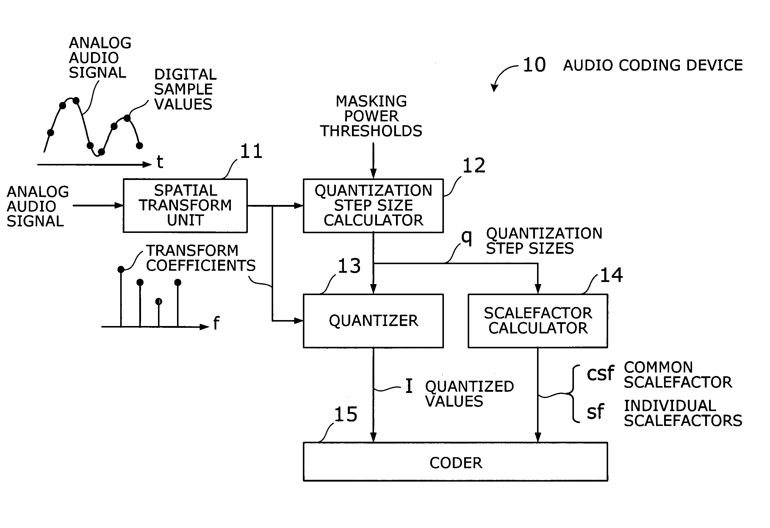
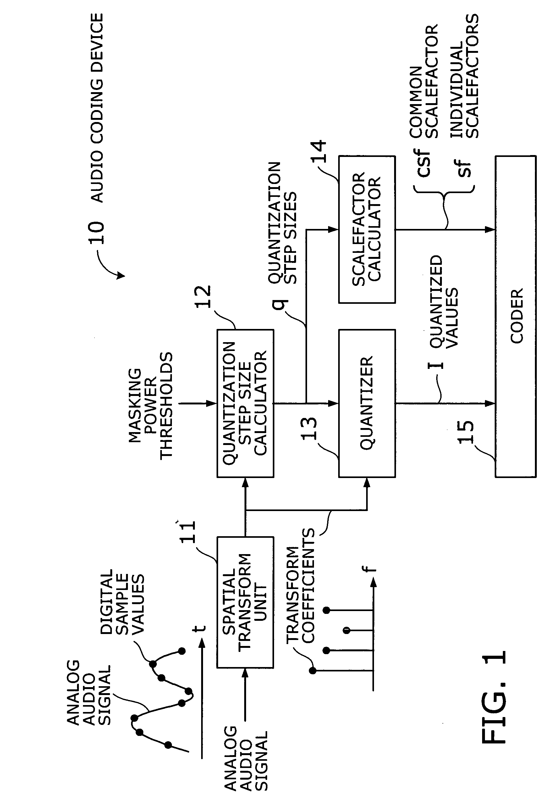
[0027]FIG. 1 is a conceptual view of an audio coding device according to an embodiment of the present invention. The illustrated audio coding device 10 is an encoder for compressing audio signal information, which has, among others, the following elements: a spatial transform unit 11, a quantization step size calculator 12, a quantizer 13, a scalefactor calculator 14, and a coder 15.

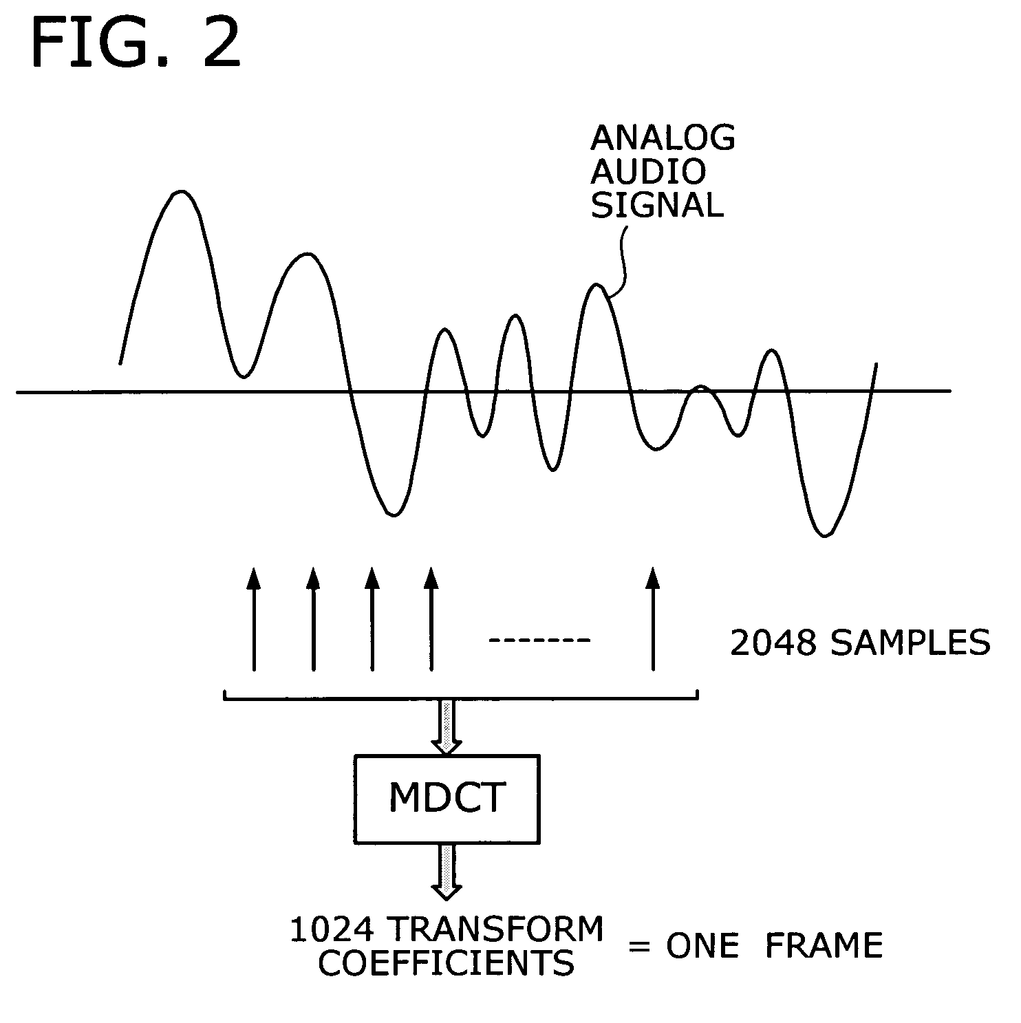
[0028] The spatial transform unit 11 subjects samples of a given audio signal to a spatial transform process. One example of such a process is the modified discrete cosine transform (MDCT). The resulting transform coefficients are divided into groups called “subbands,” depending on their frequency ranges. The quantization step size calculator 12 estimates quantization noise from a representative value selected out of...


PUM


Abstract

An efficient audio coding device that quantizes and encodes digital audio signals with a reduced amount of computation. A spatial transform unit subjects samples of a given audio signal to a spatial transform, thus obtaining transform coefficients of the signal. With a representative value selected out of the transform coefficients of each subband, a quantization step size calculator estimates quantization noise and calculates, in an approximative way, a quantization step size of each subband from the estimated quantization noise, as well as from a masking power threshold determined from a psycho-acoustic model of the human auditory system. A quantizer then quantizes the transform coefficients, based on the calculated quantization step sizes, thereby producing quantized values of those coefficients. The quantization step sizes are also used by a scalefactor calculator to calculate common and individual scalefactors. A coder encodes at least one of the quantized values, common scalefactor, and individual scalefactors.

Description

[0001] This application is a continuing application, filed under 35 U.S.C. §111(a), of International Application PCT / JP2003 / 008329, filed Jun. 30, 2003.BACKGROUND OF THE INVENTION [0002] 1. Field of the Invention [0003] The present invention relates to audio coding devices, and more particularly to an audio coding device that encodes audio signals to reduce the data size. [0004] 2. Description of the Related Art [0005] Digital audio processing technology and its applications have become familiar to us since they are widely used today in various consumer products such as mobile communications devices and compact disc (CD) players. Digital audio signals are usually compressed with an enhanced coding algorithm for the purpose of efficient delivery and storage. Such audio compression algorithms are standardized as, for example, the Moving Picture Expert Group (MPEG) specifications. [0006] Typical MPEG audio compression algorithms include MPEG1-Audio layer3 (MP3) and MPEG2-AAC (Advanced ...

Claims


Application Information

Patent Timeline
IPC IPC(8): G10L21/00G10L19/035
CPCG10L19/032G10L19/035
Inventor YAMASHITA, HIROAKI
Owner FUJITSU LTD
Learn More