
Adjustable angle pawl handle for surgical instruments

a technology of surgical instruments and pawl handles, which is applied in the field of surgical instruments, can solve problems such as difficulty in controlling the operating end of the instrument, and achieve the effects of enhancing surgical site access, facilitating use, and enhancing the degree of control of the instrumen

Inactive Publication Date: 2006-04-06
FIRST COMMERCE BANK
View PDF41 Cites 7 Cited by
  • Summary
  • Abstract
  • Description
  • Claims
  • Application Information

AI Technical Summary

Benefits of technology

[0003] It is an object of the present invention to provide an easily adjustable, angled handle for surgical instruments, which provides a better grip for the surgeon, for better overall control and manipulation of the instrument.
[0005] It is an object of the invention to provide and adjustable angle handle adaptable for use with a number of instruments, to thereby reduce the cost of adjustable angled handles for surgical instruments.
[0007] It is an object of the invention to provide a multiple user adjustable angle handle for surgical instruments, to reduce the number of handles needed in inventory, and reduce the cost of adjustable angle handles for surgical instruments.
[0012] The ability to adjust the angle of the handle with respect to the instrument shaft permits the surgeon tremendous ease of use, a far greater degree of control of the instrument, and enhanced access to surgical sites; each of which will improve the opportunity for surgical success, and may lead to the development of new surgical procedures. The angle of the handle may be adjusted by the surgical nurse or the surgeon. The angle may be readjusted mid-procedure by rotating the locking knob, and releasing the pressure on the knob, and permitting the compression spring between the proximal end of the arms of the pawl to separate the ends, and the locking jaws, releasing the shaft connector. The instrument may then be adjusted to a different angle with respect to the handle and the knob pushed forward to lock the jaws of the pawl to different set of teeth on the shaft connector. This may be easily accomplished with the two hands of a single user, without having to put the instrument down, or take it apart.

Problems solved by technology

Depending on the angle with which the force may be applied, the two-handed grip may also limit the amount of force that may be applied, and make it difficult to control the operating end of the instrument.

Method used


Image

  • Adjustable angle pawl handle for surgical instruments
  • Adjustable angle pawl handle for surgical instruments
  • Adjustable angle pawl handle for surgical instruments

Examples


Embodiment Construction

[0030] The new handles are especially advantageous for use with orthopedic surgical instruments, such as curettes, chisels, taps and probes; and most especially, with larger chisels. They may also be used with drills. New applications will be found as a result of the remarkable ease of use of the handle.

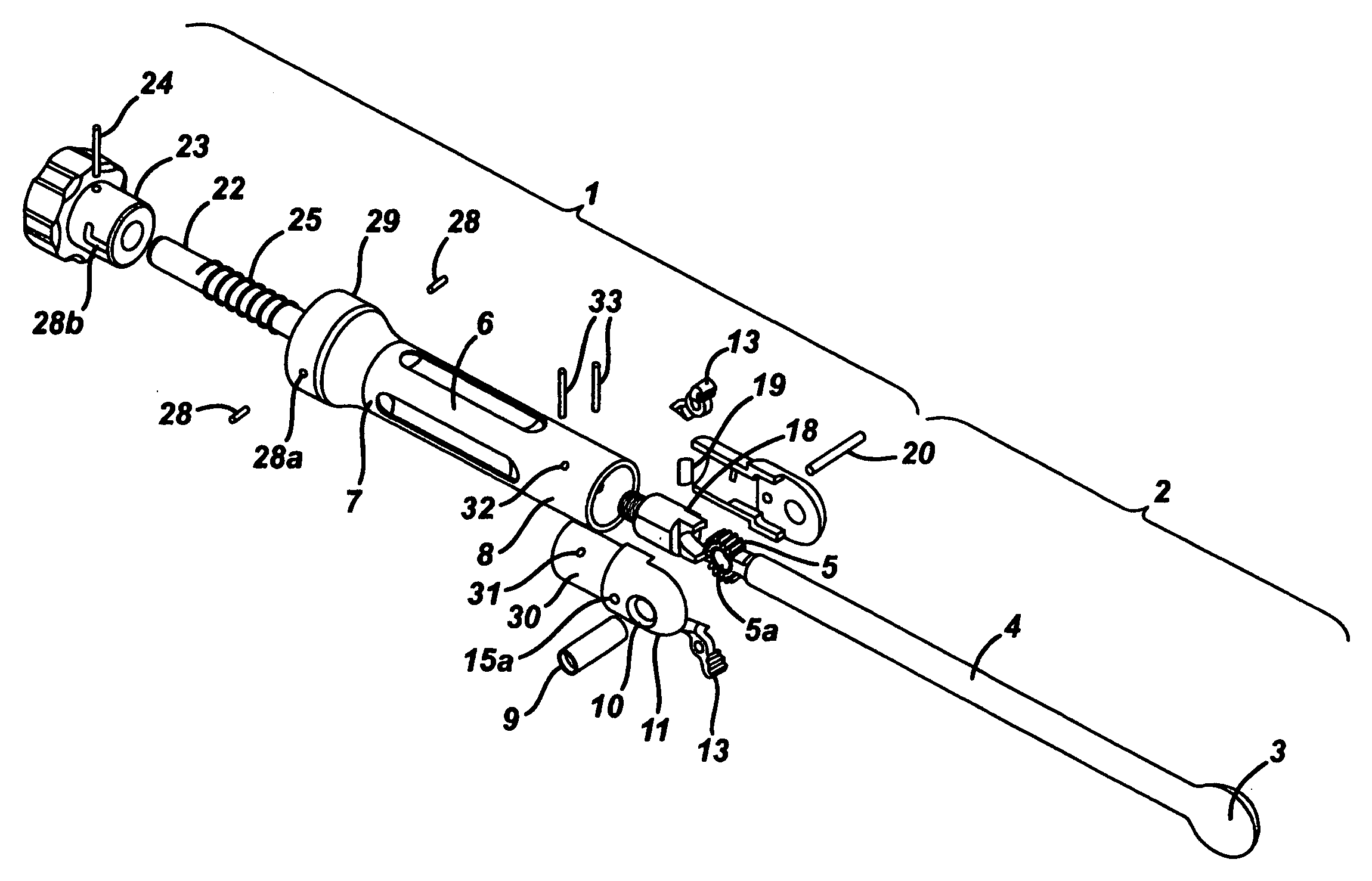
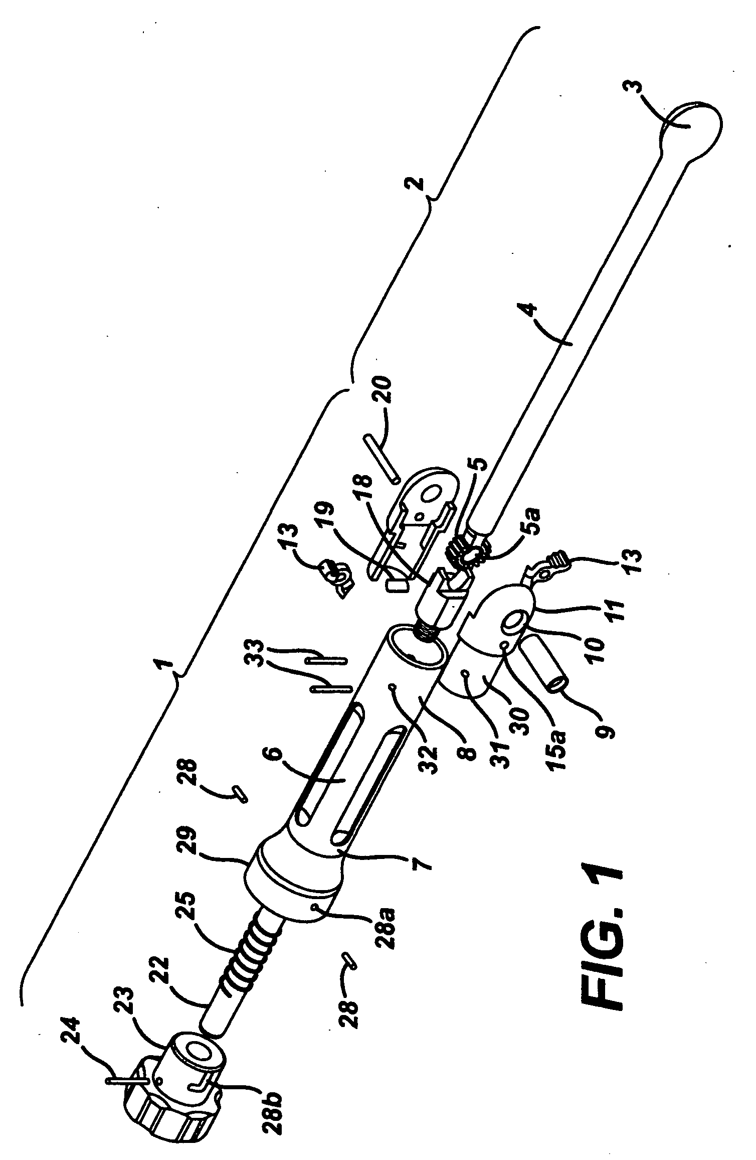
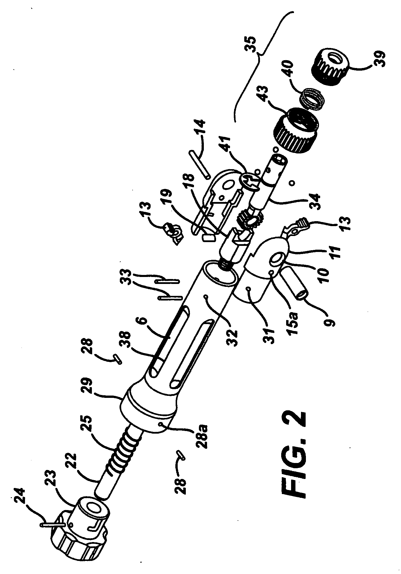
[0031] The preferred embodiments of the present invention will now be described with reference to FIGS. 1-9 of the drawings. Identical elements in the various figures are designated with the same reference numerals.

[0032]FIG. 1 illustrates an exploded perspective view of a surgical instrument with an adjustable angle handle with locking reverse scissor pawl, according to the present invention. The handle is illustrated generally at 1, and the instrument at 2. The instrument has an operating end, 3, a shaft, 4, and a shaft connecting portion, 5. The shaft connecting portion, 5, comprises a transverse bore 5a, perpendicular to the length of the shaft of the instrument, and a pluralit...


PUM


Abstract

A two piece, adjustable angle handle for a surgical instrument, capable of easy adjustment to a number of angles, permitting the handle of the instrument to be grasped with one hand, and the other hand to guide the operating end of the instrument, said handle permanently affixed to an instrument, or capable if attachment to a number of different instruments by means of a firm but releasable fastening to the shaft of the instrument, as with a Hudson fitting; the adjustable angle fastening comprising a radial array of teeth as in a ratchet wheel and a reverse scissor pawl.

Description

FIELD OF THE INVENTION [0001] The present invention relates to surgical instruments and particularly to orthopedic surgical instruments for cutting and scraping bone. BACKGROUND OF THE INVENTION [0002] When using certain orthopedic surgical instruments, such as curettes and chisels, for the removal of osteophytes, the surgeon must apply a great a degree of force. Often, this requires the surgeon to use a two handed grip on the straight handle of the instrument. Depending on the angle with which the force may be applied, the two-handed grip may also limit the amount of force that may be applied, and make it difficult to control the operating end of the instrument. In particular, when cleaning out the long bone prior to a hip implant, the surgeon generally grasps the handle of the straight curette with both hands, and moves it in an up-and-down direction. Being able to adjust the angle of the handle with respect to the shaft of the curette will give the surgeon a better angle for cutt...

Claims


Application Information

Patent Timeline
Patent Type & Authority Applications(United States)
IPC IPC(8): A61B17/16
CPCA61B17/1608A61B17/164A61B17/1659A61B2017/00424A61B2017/0046A61B2017/00464A61B2017/00473
Inventor RALPH, JAMES D.TROXELL, THOMAS N.TATER, STEPHEN L.
Owner FIRST COMMERCE BANK
Learn More