Multiplex decoding of array sensors with microspheres
a technology of array sensors and microspheres, applied in the field of decoding microsphere array sensors, can solve the problem of requiring a set of unique optical signatures, and achieve the effect of reducing the overall length of the prob
- Summary
- Abstract
- Description
- Claims
- Application Information
AI Technical Summary
Benefits of technology
Problems solved by technology
Method used
Image
Examples
example 1
[0315] Sixteen microspheres (beads) were labeled combinatorially with two different fluorophores (FAM and Cy3). In a first round of labeling, either FAM or Cy3-labeled oligonucleotides that were complementary to the oligonucleotide (IBL) on the microsphere, were hybridized with the microsphere. Labeling of oligonucleotides was performed as is well known in the art. Hybridization conditions are known in the art.
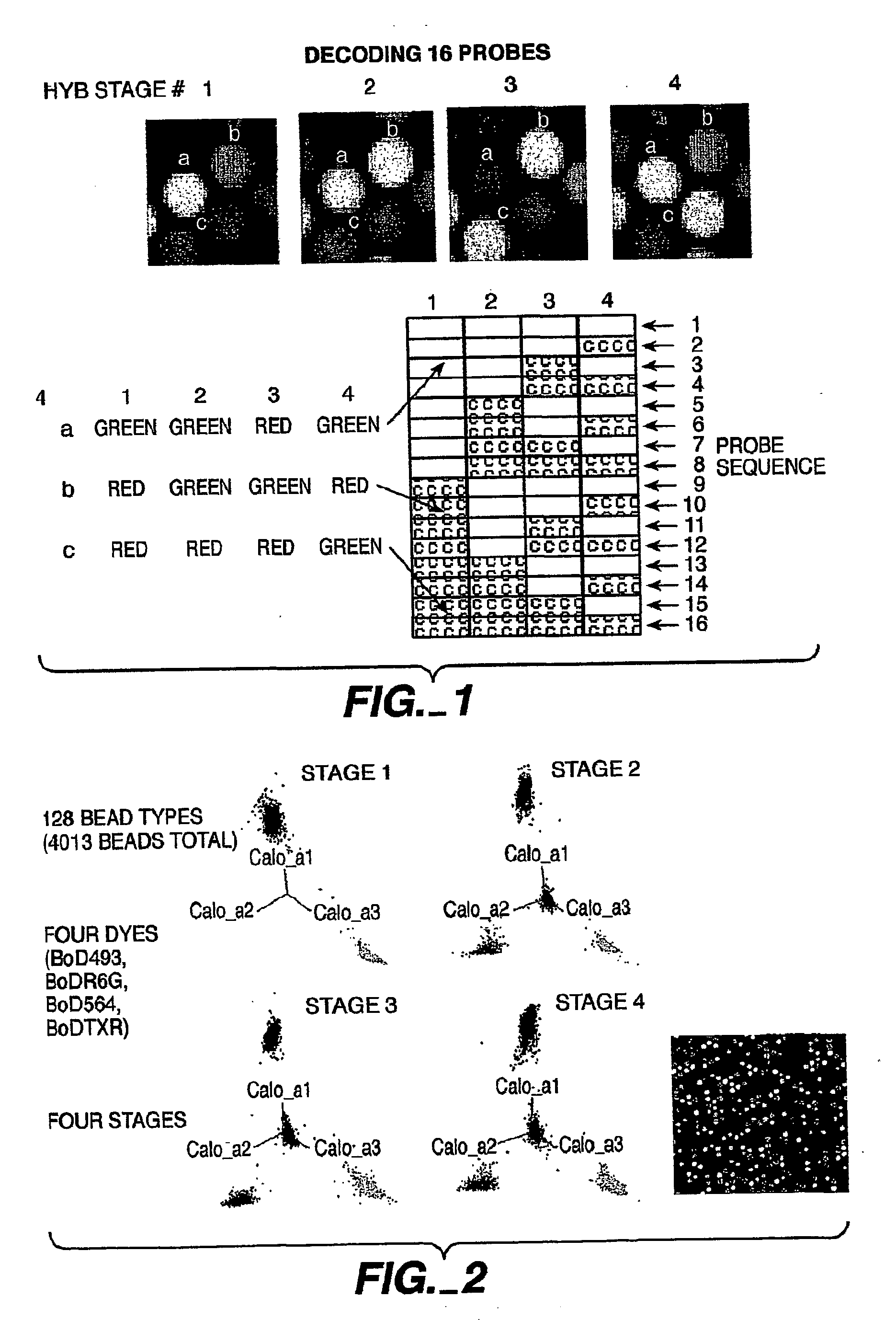
[0316] Following a first round of hybridization, the two pools of beads were divided into two pools each and each labeled either with the FAM or Cy3-labeled oligonucleotide. This process was repeated two additional times. Thus, following four successive rounds of labeling, each microsphere was labeled with a unique code (see FIG. 1). The identity of each microsphere was elucidated by determining the identity of each fluorophore in succession; the terminal fluorophere was determined and then removed to allow for the identification of the next fluorophore. In this fashion, with...
example 2
[0317] A decoding scheme similar to that described in Example 1 was implemented for four color decoding. In this example, beads were labeled as described in Example 1 with the exception that 4 labels were used at each stage. 4013 beads were labeled using Bod493, BodR6G, Bod564 and BodTXR labeled oligonucleotides. 128 different bead types were identified based on the successive decoding of the four colors.
example 3
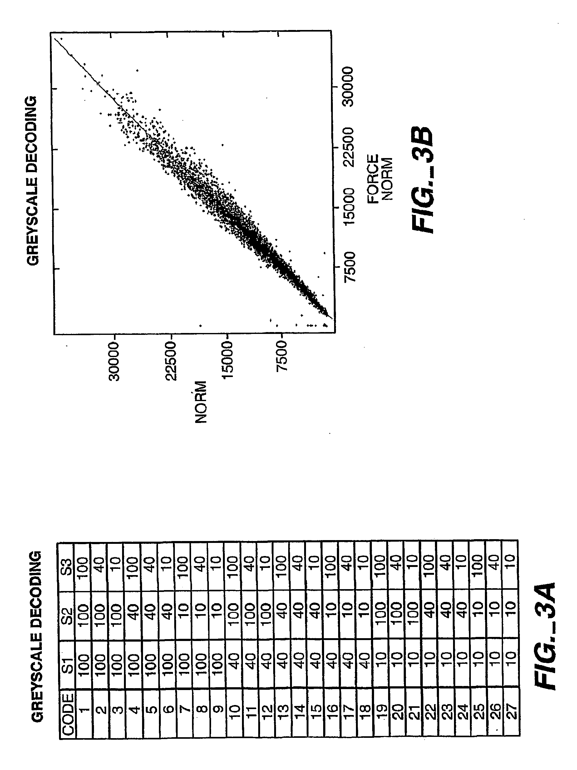
[0318] An alternative method to using multiple colors is to use ratiometric intensities as a coding scheme. A normalizing image is acquired in which every bead exhibits its “full” intensity. Subsequent decode stages generate intensity codes by hybridizing mixtures of “labeled”:“unlabeled” complementary oligonucleotides. For instance, FIG. 1 depicts three different intensity shades (low, medium, and high) which can be ratioed to a stage with all complements present at a “high” shading value. An experiment using grey scale decoding on 16 different bead types is shown in FIG. 3.
[0319]FIG. 3A depicts the combinatorial pooling scheme for labeling beads with different ratios of labeled oligonucleotides. A particular oligo is present at either 100% Cy3-labeled, 40% Cy3-labeled (60% unlabeled), or 10% Cy3-labeled (90% unlabeled) fraction. Decode oligos were hybridized to the array for 2 min. at a 50 nM concentration. Subsequently, two independent normalizing images (all oligo complements a...
PUM
| Property | Measurement | Unit |
|---|---|---|
| sizes | aaaaa | aaaaa |
| sizes | aaaaa | aaaaa |
| sizes | aaaaa | aaaaa |
Abstract
Description
Claims
Application Information
 - R&D
- Intellectual Property
- Life Sciences
- Materials
- Tech Scout
- Unparalleled Data Quality
- Higher Quality Content
- 60% Fewer Hallucinations
Browse by: Latest US Patents, China's latest patents, Technical Efficacy Thesaurus, Application Domain, Technology Topic, Popular Technical Reports.
© 2025 PatSnap. All rights reserved.Legal|Privacy policy|Modern Slavery Act Transparency Statement|Sitemap|About US| Contact US: help@patsnap.com


