Keyboard apparatus
a technology of keyboard and spherical body, applied in the field of keyboard apparatus, can solve the problems of sudden decrease in the amount of bend, and achieve the effect of simplifying construction and ensuring load chang
- Summary
- Abstract
- Description
- Claims
- Application Information
AI Technical Summary
Benefits of technology
Problems solved by technology
Method used
Image
Examples
first embodiment
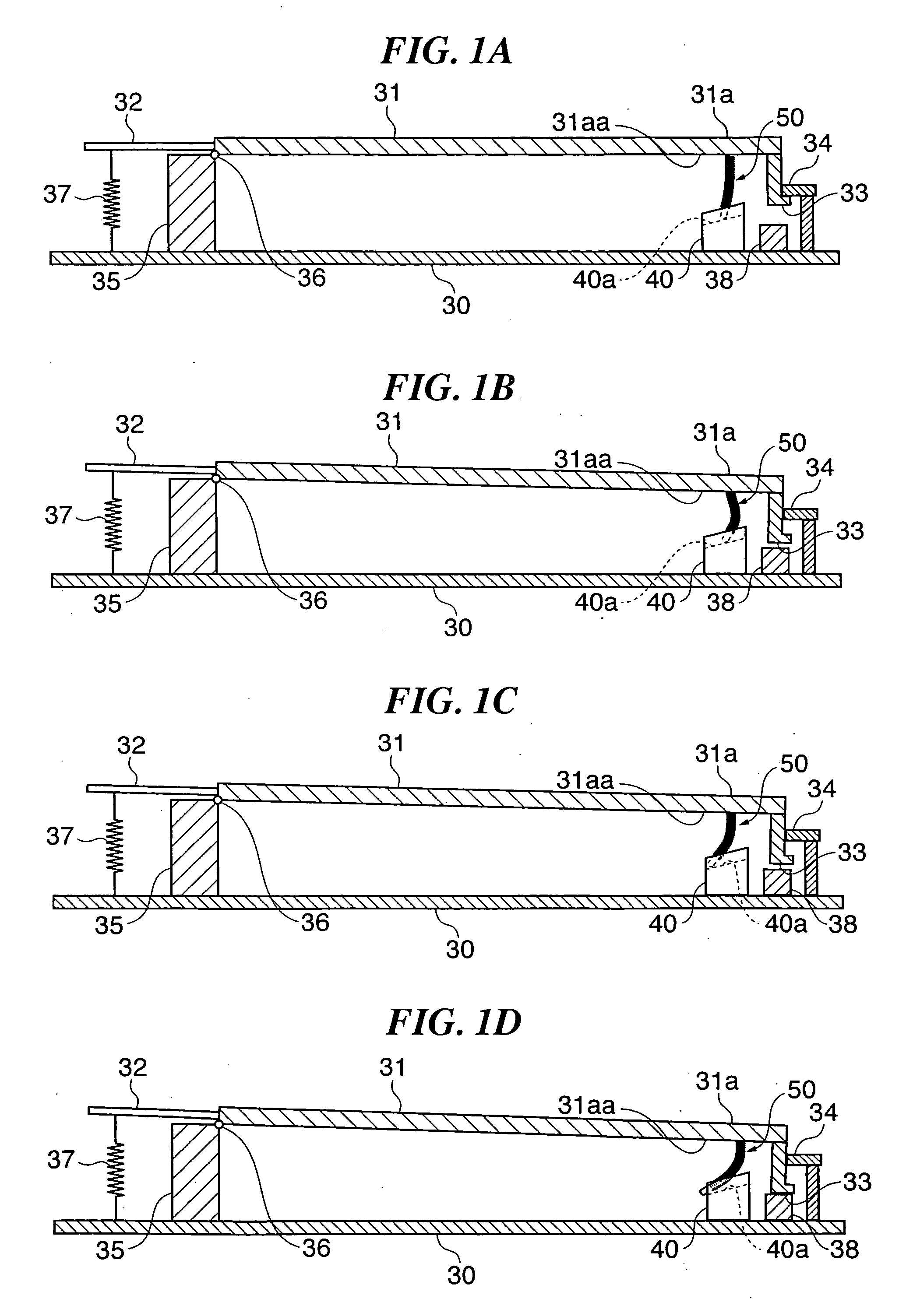
[0071]FIGS. 1A to 1D are longitudinal cross-sectional views of a keyboard apparatus according to the present invention. FIG. 1A shows the keyboard apparatus in a non-key-depressed state; FIGS. 1B and 1C show the same in states during key depression; and FIG. 1D shows the same in a key depression-terminated state. As shown in FIG. 1A, a support member 30 has a support column 35 as a key support provided thereon, and a key body 31 is supported by the support column 35 for vertical swinging motion about a pivot 36 provided on the top of the support column 35. In the following description, a free end side of the key body 31 (right side as viewed in FIG. 1A) will be referred to as “the front side”. In FIGS. 1A to 1D, a white key is shown as the key body 31, by way of example.
[0072] An extended part 32 extends rearward from the pivot 36 of the key body 31, and a key return spring 37 is stretched as a key return device between the extended part 32 and the support member 30, for always pull...
second embodiment
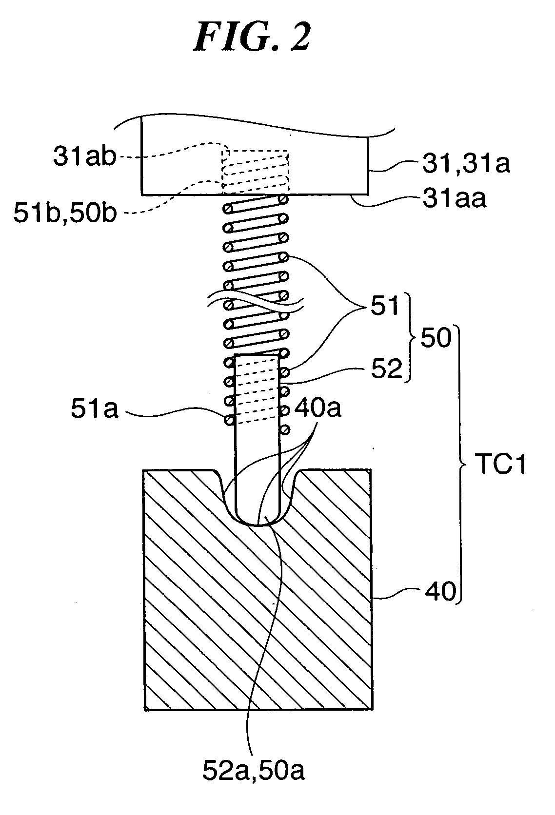
[0082] More specifically, the lower end 50a of the elastic engaging unit 50 and the guide rail 40a are in a state where an appropriate friction is produced therebetween, and the static frictional state between them is maintained from the state shown in FIG. 3A to the state shown in FIG. 3B. Further, when the key touch feeling-imparting mechanism is in the state shown in FIG. 3B, the position of the key operating part 31a is lower than when the same is in the state in FIG. 3A, and hence the elastic engaging unit 50 (specifically, the coil spring 51) is further bent such that it generally protrudes in the same direction (toward the front side) as it does beforehand. Hereafter, the increase in the amount of bend described above will be referred to as “additional bend”, in the present embodiment as well as a second embodiment described hereinafter. The reaction force produced by the additional bend of the coil spring 51 acts on the key body 31, and insofar as the static frictional state...
third embodiment
[0132] Next, a description will be given of the present invention.
[0133] A keyboard apparatus according to the third embodiment of the present invention is distinguished from the keyboard apparatus according to the second embodiment in the constructions of the key touch feeling-imparting mechanism, fixing members associated therewith, and the like, but otherwise has the same construction as that of the second embodiment.
[0134]FIG. 6A is a side view of a key touch feeling-imparting mechanism TC3 of the keyboard apparatus according to the third embodiment. FIG. 6B is a fragmentary side view of a key touch feeling-imparting mechanism TC4 as a variation of the keyboard apparatus according to the third embodiment.
[0135] A common base 80 shown in FIG. 6A is constructed similarly to the common base 60 of the second embodiment, and has a white key-receiving part 80aW and a black key-receiving part 80aB corresponding to the white key-receiving part 60aW and the black key-receiving part 60a...
PUM
 Abstract
Description
Claims
Application Information
 - R&D
- Intellectual Property
- Life Sciences
- Materials
- Tech Scout
- Unparalleled Data Quality
- Higher Quality Content
- 60% Fewer Hallucinations
Browse by: Latest US Patents, China's latest patents, Technical Efficacy Thesaurus, Application Domain, Technology Topic, Popular Technical Reports.
© 2025 PatSnap. All rights reserved.Legal|Privacy policy|Modern Slavery Act Transparency Statement|Sitemap|About US| Contact US: help@patsnap.com


