
Pile testing reaction anchor apparatus and method

a technology of reaction anchors and piles, applied in the direction of instruments, structural/machine measurement, elasticity measurement, etc., can solve the problems of large installation cost of driving into the soil one, two, or more pairs of anchor piles, and difficulty in handling the long and heavy anchor piles required

Inactive Publication Date: 2006-04-06
METAL FOUND ACQUISITION
View PDF7 Cites 8 Cited by
  • Summary
  • Abstract
  • Description
  • Claims
  • Application Information

AI Technical Summary

Problems solved by technology

It is extremely difficult and expensive to pull those anchor piles out of the ground.
One drawback of the conventional pile testing apparatus and methods is the large installation cost of driving into the soil one, two, or more pairs of anchor piles per each single pile or group of piles to be tested.
Another drawback of the conventional pile testings is the difficulty in handling the long and heavy anchor piles required for the testings, e.g., requiring a tractor and a trailer for their transportation, requiring a special crane for lifting in or out of the trailer, requiring an expensive, cumbersome pile driving machine for driving the anchor piles into the ground.
Another drawback of the conventional pile testings is the difficulty of setting the long and heavy anchor piles in a vertical position for driving them into the ground.
Yet another drawback of the conventional pile testings is the loss of the anchor piles, because after the test is completed, they are not reusable in future tests, and therefore, their top ends protruding above the ground have to be sawed off, abandoning the pile in the ground.

Method used


Image

  • Pile testing reaction anchor apparatus and method
  • Pile testing reaction anchor apparatus and method
  • Pile testing reaction anchor apparatus and method

Examples


Embodiment Construction

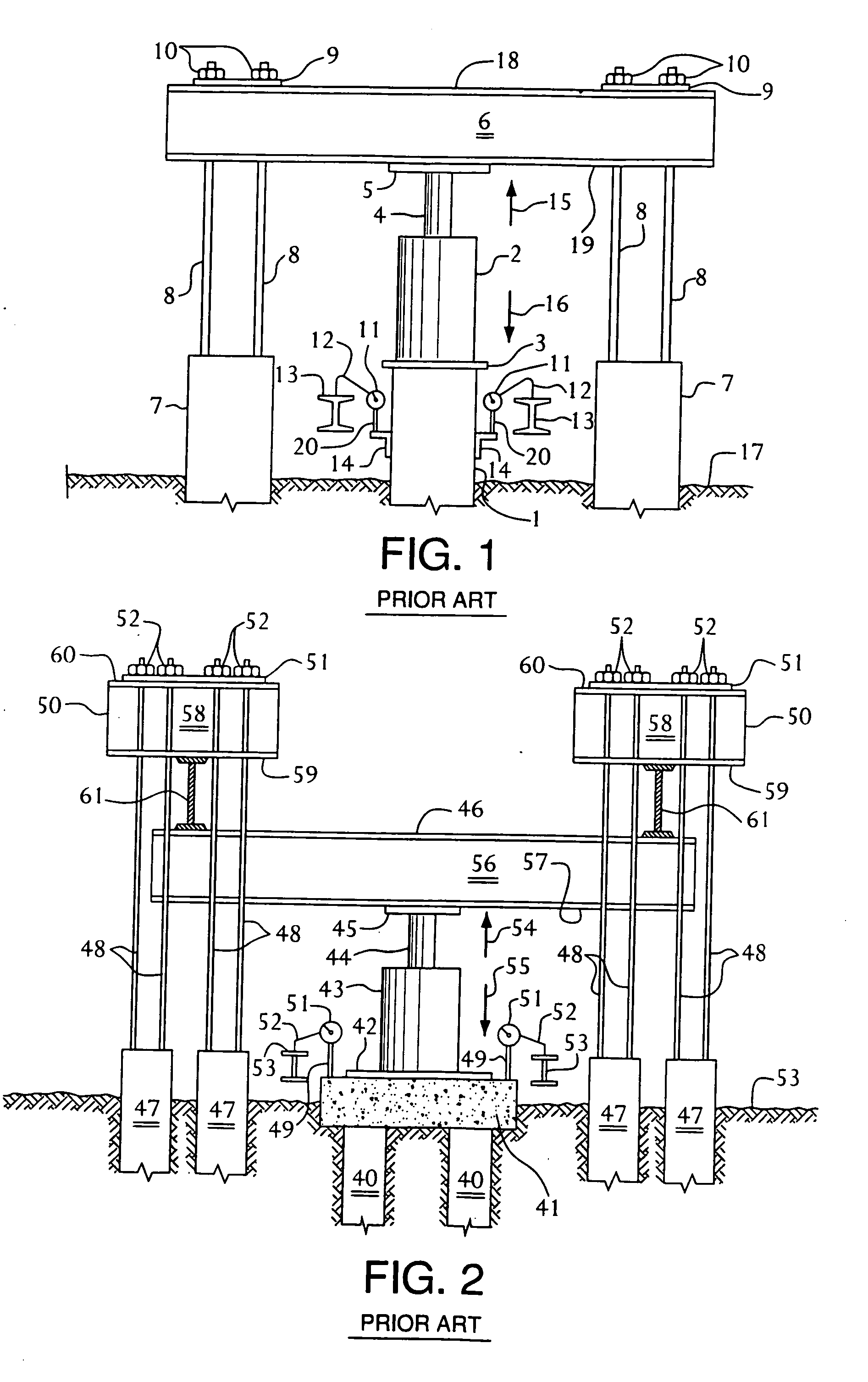
[0040]FIG. 1 and FIG. 2 depict apparatus and method representing the conventional testing apparatus and method for testing vertical piles, as shown on ASTM D1143-81(reapproved 1987). FIG. 1 depicts the conventional testing apparatus and method for testing a single pile. FIG. 2 depicts the conventional testing apparatus and method for testing a group of piles.

[0041] Referring now to FIG. 1, a single pile 1 is shown as having been driven into soil 17. A pair of anchor piles 7 also have been driven into soil 17, at a distance at least seven feet away from or clear of pile 1, i.e., away from the pile 1 under test. A bottom flange 19 of a test beam 6 is set on top of a bearing plate 5 of a piston ram 4 of a hydraulic cylinder 2. The hydraulic cylinder 2 is set on a test plate 3, which is centered on top of the individual pile 1, i.e., the single pile 1.

[0042] The test beam 6 is tied to the anchor piles 7 by means of a series of connecting rods 8, a pair of plates 9 on a top flange 18 o...


PUM


Abstract

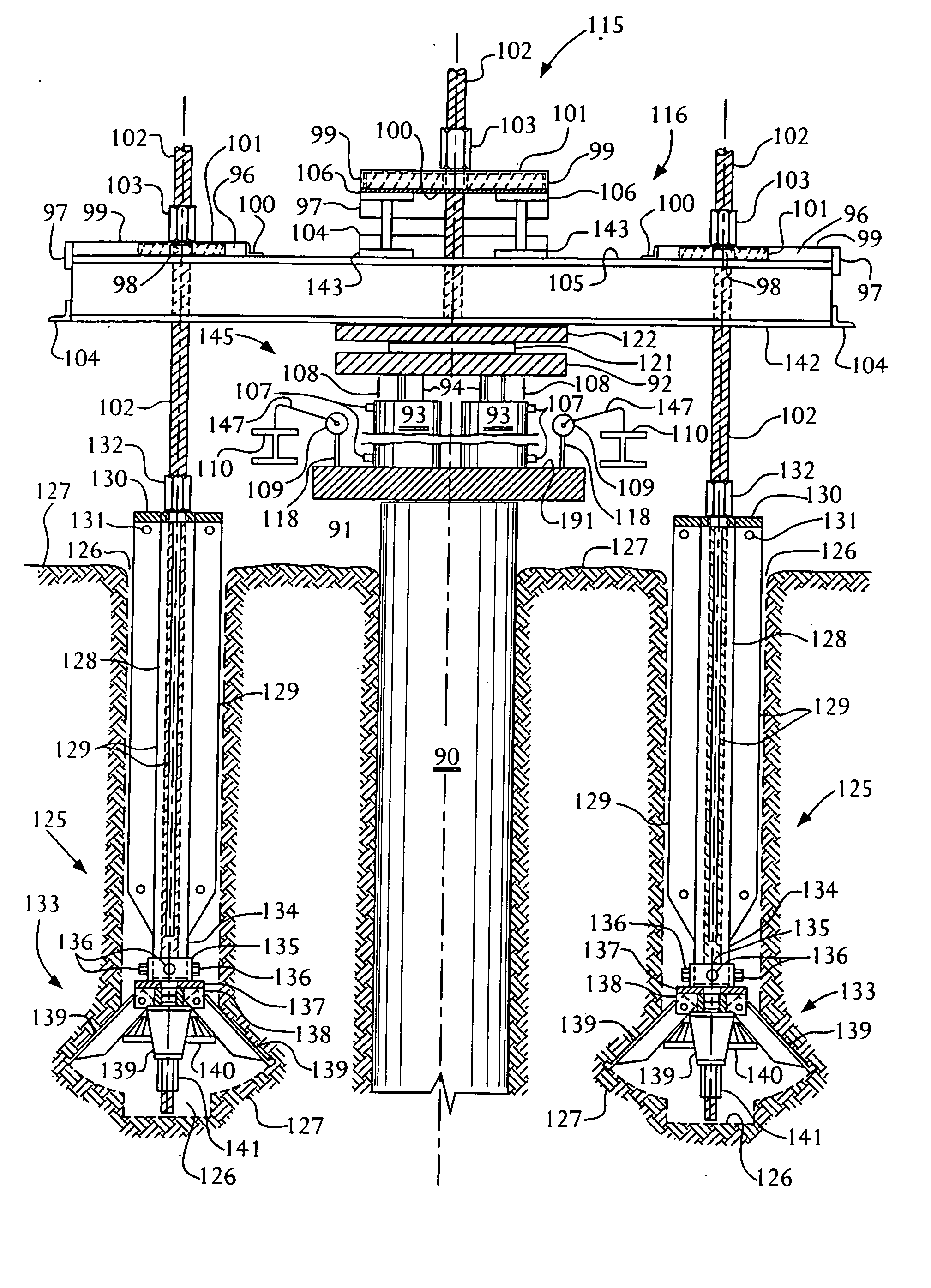
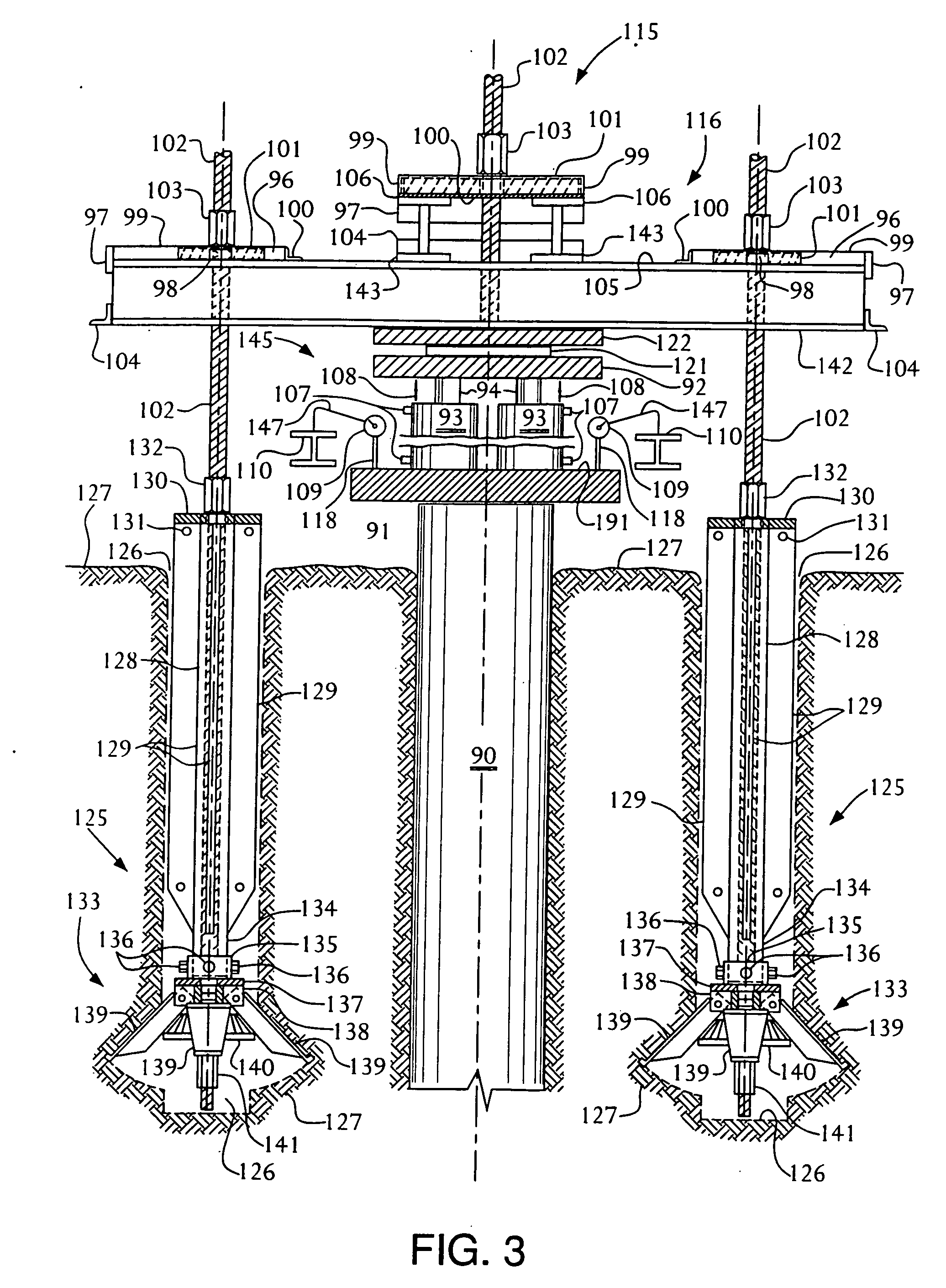
Pile testing apparatus and method apply static compressive forces on a pile to be tested for load bearing capacity. Retractable and reusable reaction anchor assemblies are installed into the ground for pile testing and then are retrieved from the ground after completion of the pile testing and are reused from one pile test site to another. The invention operates to receive an equal and opposite reaction force on an I-beam and provide at least two retractable and reusable reaction anchor assemblies installed into the ground at a depth significantly less than required with conventional pile testing methods. The I-beam is braced by the two retractable and reusable reaction anchor assemblies and held stationary in counter-action against the opposite reaction force on the I-beam. The pile testing apparatus and method of the present invention reduce costs considerably and can be used immediately as contrasted to conventional methods using concrete.

Description

BACKGROUND OF THE INVENTION [0001] 1. Technical Field [0002] This invention relates to an apparatus and method for testing load bearing capacity on a pile or group of piles. In one aspect, this invention relates to novel apparatus and method for testing load bearing capacity on a pile or group of piles, utilizing a reaction anchor apparatus and method. [0003] 2. Background [0004] In the construction industry, various types and shapes of piles are utilized for constructing foundations on the piles. These foundations are the structural supports upon which many types of constructions are built. Foundations support the loads imposed upon them and, hence, the loads imposed upon the piles, by such constructions as high rise buildings, power plants, river dams, and many other constructions. [0005] Among the most common types and shapes of piles are timber piles, steel pipe piles, H-Piles, L-Piles, precast concrete piles, and cast-in-place concrete piles. These piles are installed verticall...

Claims


Application Information

Patent Timeline
IPC IPC(8): G01N3/08E02D33/00G01M5/00G01N3/00
CPCE02D33/00G01M5/005G01N2203/0019
Inventor REINERT, GARY L. SR.
Owner METAL FOUND ACQUISITION
Learn More