
Dental handpiece with a root canal length measurement function

a technology of handpiece and function, applied in the field of handpiece, can solve the problems of limiting the manageability of the handpiece, increasing the manufacturing cost of coating, and the inability to meet the prevailing ambient conditions of plastics used for coating or as a material for the handle sleeve section,

Inactive Publication Date: 2006-03-30
W&H DENTALWERK
View PDF6 Cites 7 Cited by
  • Summary
  • Abstract
  • Description
  • Claims
  • Application Information

AI Technical Summary

Benefits of technology

The present patent describes a handpiece for dental instruments that has an outer sleeve made of non-insulating metal material, without any coating. This makes it insensitive to the sterilization process. All components of the handpiece that are in contact with the instrument are insulated from the outer sleeve to ensure accurate measurement of root canal length and signal line integrity. The contact device is designed to make physical contact with the dental instrument outside of the handpiece. This design prevents any electrical current from leaking into the dental instrument, which could cause damage or malfunction.

Problems solved by technology

The disadvantage with this arrangement is the conducting wire is attached to the sleeve of the handpiece handle, which restricts the manageability of the handpiece.
These known handpieces have the disadvantage on the one hand of the greater manufacturing costs due to the coating and on the other hand that plastics used for coating or as a material for the handle sleeve sections are not stable relative to the prevailing ambient conditions for sterilization, particularly steam-sterilization.
Since however the handpieces must be sterilized following each use, the life of such coatings or handle sleeve sections is very limited.
In particular, the handpiece must be insensitive to the prevailing ambient conditions for sterilization.
In relation to the prevailing ambient conditions for sterilization, it is therefore insensitive.

Method used


Image

  • Dental handpiece with a root canal length measurement function
  • Dental handpiece with a root canal length measurement function
  • Dental handpiece with a root canal length measurement function

Examples


Embodiment Construction

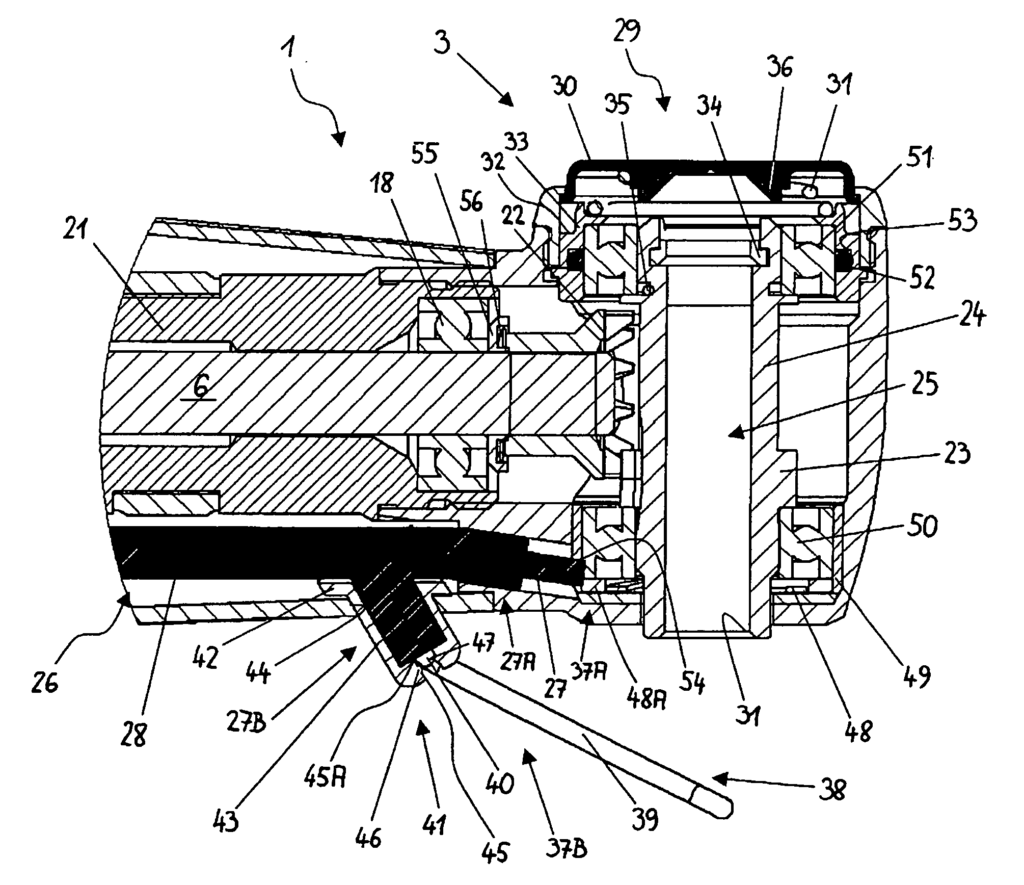
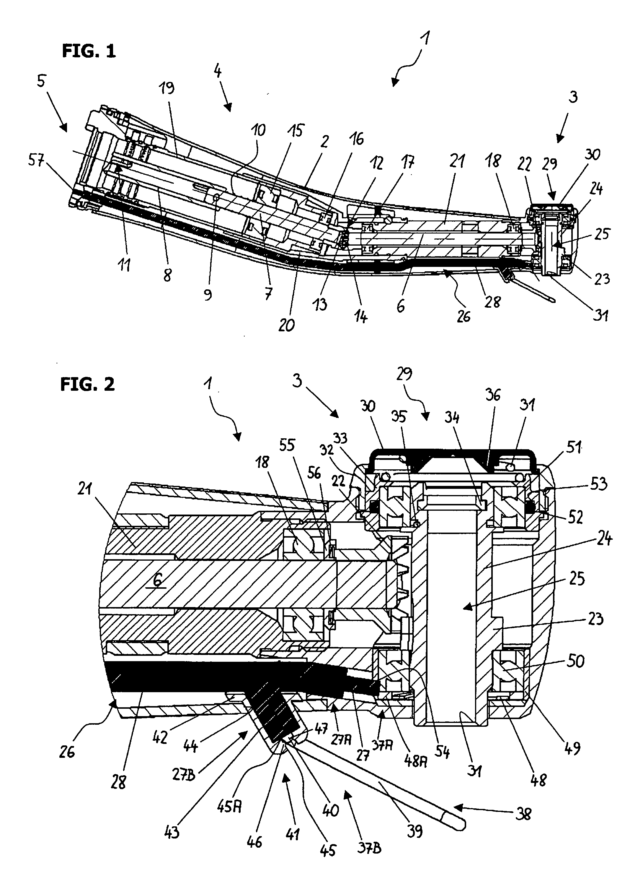
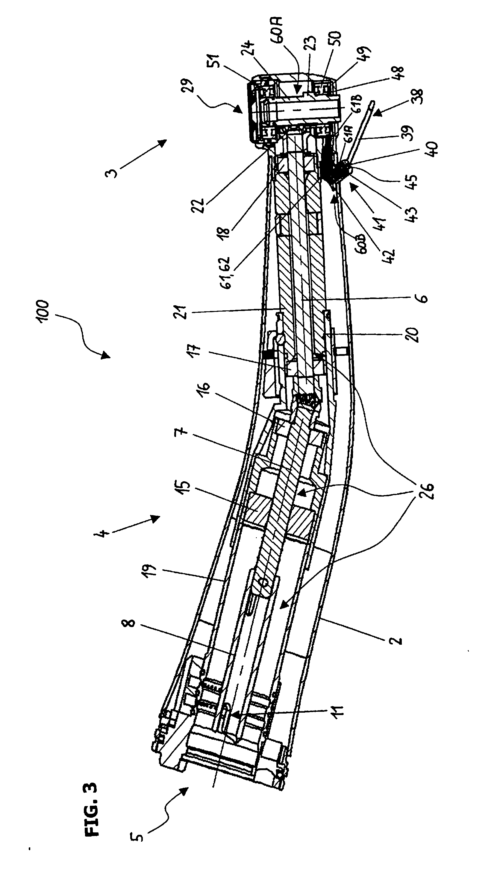
[0017] The contra-angle handpiece 1 illustrated in FIG. 1 is comprised of an outer sleeve 2 with a head section 3 and a handle section 4. The entire outer sleeve 2 (including pushbutton 29) is not insulating, i.e. it is made substantially of a non-insulating, preferably metallic, material and also has substantially no insulating coating. At the proximal end of the outer sleeve 2 is a connecting device 5 for coupling the handpiece to a control and evaluation unit, a measuring circuit with a current source for the measurement of the root canal length and drive unit. The connecting device 5 is preferably designed in the form of the twist-on connection familiar to dental specialists, so that no further description is necessary here.

[0018] As used herein, the terms “non-conductive,”“insulating” and “insulated” mean that the component or material so described reduces or prevents the transmission of electricity. Conversely, the terms “conductive,”“conducting” and “non-insulating” mean tha...


PUM


Abstract

A handpiece for measuring root canal length comprises an outer sleeve that is substantially non-insulating, a connecting device, an instrument carrier, at least one transmission element within the outer sleeve, a length measuring circuit portion, a contact portion and an insulating portion. The instrument carrier is configured to receive a dental instrument. The transmission element transmits force to move the instrument carrier so that a dental instrument received in the instrument carrier executes a rotating, reciprocating and / or vibrating working movement. The length measuring circuit portion is disposed inside the handpiece and operable to transmit measuring signals for measuring length. The contact portion is operable to establish a conductive path between the dental instrument serving as an electrode and the length measuring circuit portion. The insulating portion insulates the length measurement circuit portion and the contact device, through which a voltage is applied during measurement, from the outer sleeve.

Description

CROSS REFERENCE TO RELATED APPLICATION [0001] The present application claims priority from pending European Patent Application No 04023260.5, filed Sep. 30, 2004, which is incorporated herein by reference. BACKGROUND [0002] 1. Field [0003] The present application concerns a dental handpiece for the treatment of root canals and the measurement of the root canal length. [0004] 2. Description of Prior Art [0005] Such a handpiece is part of a device for the determination of the length (depth) of a root canal and of the position of the treatment instrument attached to the handpiece, respectively. The device comprises, together with the handpiece, two electrodes and a control and evaluation unit. The first electrode, usually in the form of a clip-on electrode, is attached to the oral mucosa of the patient. The instrument attached to the handpiece, for example a file moving back and forth (executing reciprocating movements), a reamer or a rotating dental drill, serves as the second electro...

Claims


Application Information

Patent Timeline
Patent Type & Authority Applications(United States)
IPC IPC(8): A61C1/00A61C19/04
CPCA61C19/041A61C1/084
Inventor EIBL, JOHANNBRANDSTAETTER, ANDREAS
Owner W&H DENTALWERK
Learn More