
Control system of molding machine

a molding machine and control system technology, applied in the direction of process control, process control, instruments, etc., can solve the problems of not being able to completely change all the components, the change of the program or the system is not easy, and the cost of the facility is high, so as to improve productivity and work efficiently. , the effect of low cos

Active Publication Date: 2006-03-30
TOSHIBA MASCH CO LTD
View PDF10 Cites 28 Cited by
  • Summary
  • Abstract
  • Description
  • Claims
  • Application Information

AI Technical Summary

Benefits of technology

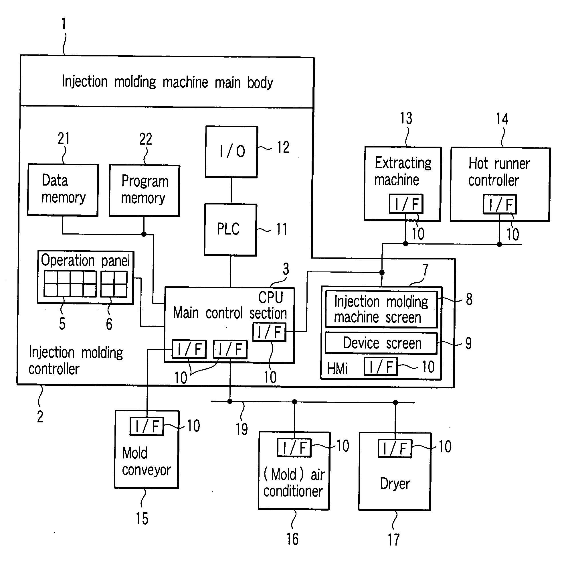
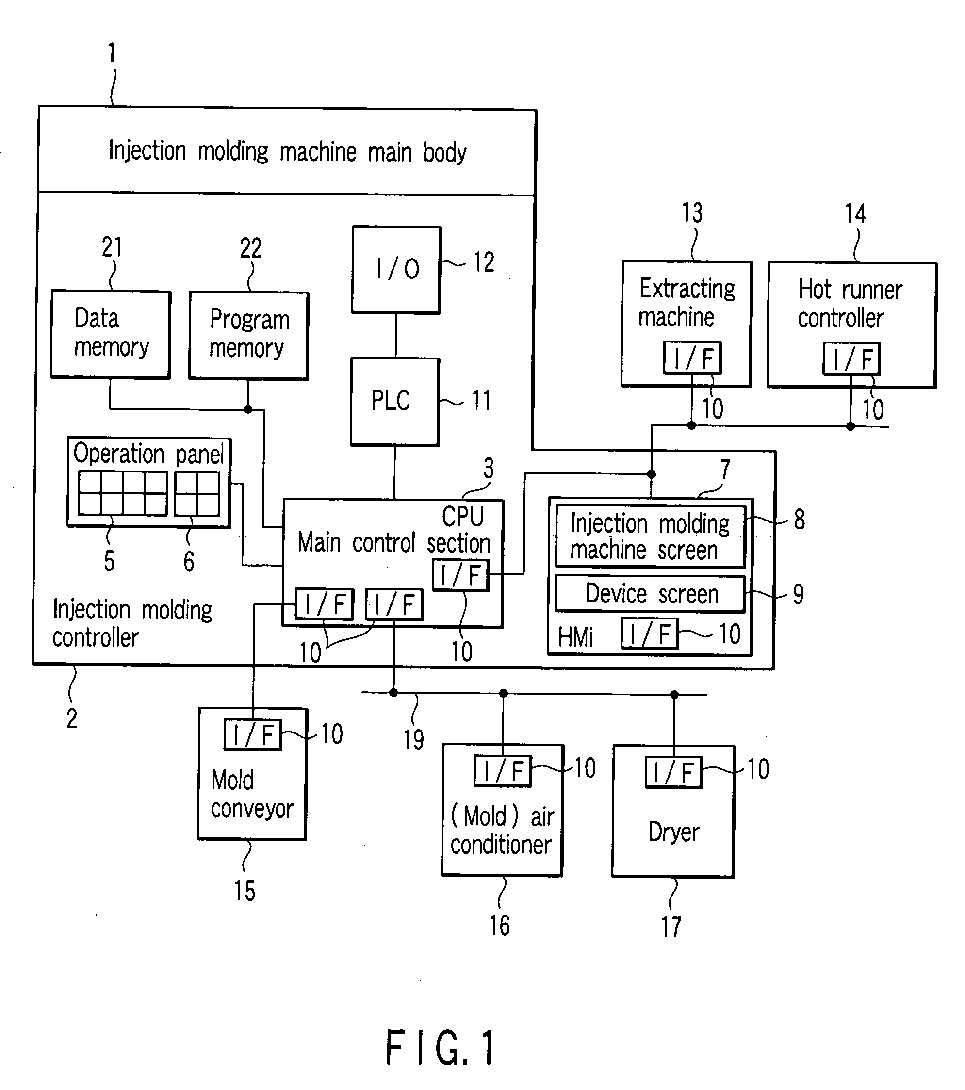
[0013] The present invention provides a control system of a molding machine which is constructed by a plurality of injection molding machines and peripheral devices thereof and which is capable of realizing a working environment at a low cost and with a high working efficiency mainly by the respective injection molding machines and which has an improved productivity.

Problems solved by technology

Accordingly, facility costs are high, and changing of the program or the system is not easy because of lack of flexibility.
In other words, the system cannot be changed corresponding to improvements of each injection molding machine and the peripheral device thereof or higher performance by a new device model, creating a problem that it will be necessary to completely change all the components.
As a management operation and the program become complex, even the host computer can only execute setting at the controller of the site terminal or monitoring of the site terminal, and many control systems have no functions of controlling the peripheral devices thereof.
Under such a situation, an operator moves to its installation position for each checking of an operation state or operation of the peripheral device, causing not only an increase in wastes of time but also a molding failure which may occur due to resin staying or the like.
For example, when a set temperature of a temperature controller installed on an opposite operation side of the injection molding machine is changed, the operator moves away from the controller of the injection molding machine, and cannot instantaneously determine an influence on a molding process by the changed set temperature of the temperature controller.

Method used


Image

  • Control system of molding machine
  • Control system of molding machine
  • Control system of molding machine

Examples


Embodiment Construction

[0024] Hereinafter, an embodiment of the present invention will be described in detail with reference to the accompanying drawings.

[0025] First, a concept of constructing a control system of a molding machine of the present invention will be described.

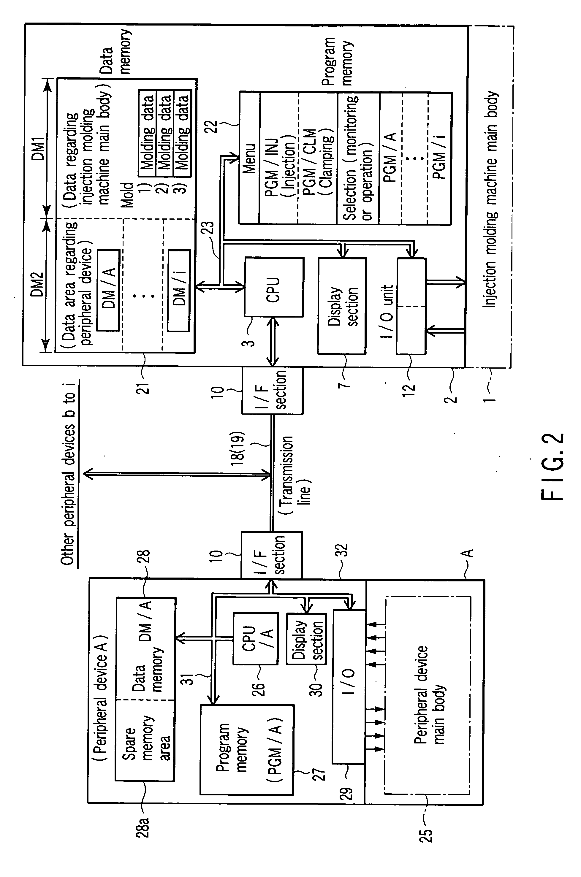
[0026] An injection molding machine and each peripheral device used for the control system of the molding machine of the present invention are connected through a general communication line such as Ethernet (registered trademark), a USB, serial communication, a MODBUS or the like, and a communication protocol or a control command is defined beforehand to communicate data between each peripheral device and the injection molding machine. The peripheral device and the injection molding machine for which a control program is created in accordance with the definition can communicate data only by making connections through defined communication means, e.g., transfer a file containing information regarding operation conditions. A controller...


PUM

PropertyMeasurementUnit
Temperatureaaaaaaaaaa
Pressureaaaaaaaaaa
Speedaaaaaaaaaa

Abstract

There is disclosed a control system of an injection molding machine in which a controller mounted on a main body side of an injection molding machine comprises a data memory having a memory area to always reflect information regarding a plurality of operation conditions and operation situations corresponding to peripheral devices, and a program to give a desired command to the peripheral devices, and a control section of the peripheral devices and the controller on the injection molding machine main body side comprise a data transmission line to always reflect information regarding the operation conditions and the operation situations, and a transmission control section equipped with a protocol regarding a signal transmitted through the transmission line.

Description

CROSS-REFERENCE TO RELATED APPLICATIONS [0001] This application is based upon and claims the benefit of priority from prior Japanese Patent Application No. 2004-277875, filed Sep. 24, 2004, the entire contents of which are incorporated herein by reference. BACKGROUND OF THE INVENTION [0002] 1. Field of the Invention [0003] The present invention relates to a control system of a molding machine which shares operation signals between it and peripheral devices thereof with an injection molding machine. [0004] 2. Description of the Related Art [0005] Generally, for an injection molding machine for manufacturing various articles by injection molding using resin materials or the like, a plurality of peripheral devices are connected to a main control section of a molding machine main body. As peripheral devices, there are available a takeout robot, a hot runner controller, a dryer, a mold, a temperature controller of a heating cylinder of an injection device, a conveyor, and the like. A pro...

Claims


Application Information

Patent Timeline
IPC IPC(8): B29C35/08
CPCB29C45/76B29C2945/76531B29C2945/76668B29C2945/76752B29C2945/76792G05B2219/45244B29C2945/76869B29C2945/76939B29C2945/76993G05B2219/31457B29C2945/76859
Inventor NISHIZAWA, MAKOTO
Owner TOSHIBA MASCH CO LTD
Learn More