
Belt fuser assembly with heated backup roll in an electrophotographic imaging device

a technology of electrophotographic imaging and belt fuser, which is applied in the direction of electrographic process apparatus, instruments, optics, etc., can solve the problems of inability to meet the requirements of conventional roller fusers, inability to keep the belt temperature high, and slowing down printing speed, so as to reduce paper curl, improve thermal extendibility, and reduce the effect of paper curl

Inactive Publication Date: 2006-03-30
LEXMARK INT INC
View PDF24 Cites 12 Cited by
  • Summary
  • Abstract
  • Description
  • Claims
  • Application Information

AI Technical Summary

Benefits of technology

[0014] An advantage of the present invention is that the belt fuser and heated backup roll combination provides a higher thermal extendibility to allow the belt fuser to meet high speed printing requirements.
[0015] Another advantage is that the belt fuser with heated backup roll reduces paper curl.
[0016] Yet another advantage is that the belt fuser with heated backup roll eliminates belt stalls due to water condensation on the backup roll.
[0017] A further advantage is that the belt fuser with heated backup roll allows for higher gloss printing at printing speeds of 32 pages per minute or greater.

Problems solved by technology

Conventional roller fusers are unable to meet this requirement due to large thermal masses.
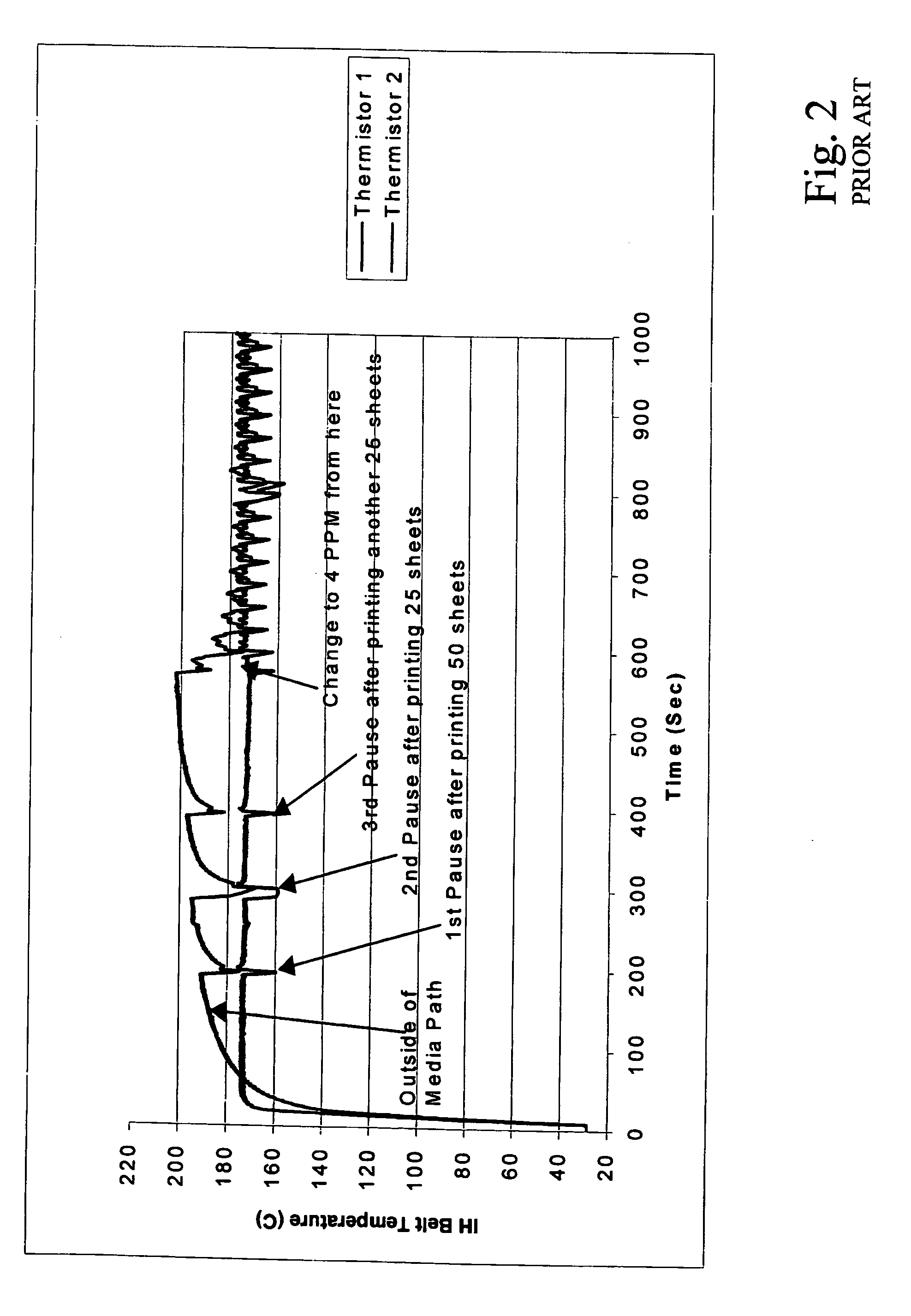
Either the belt temperature cannot be kept high enough to achieve good fusing quality for high speed printing or the printing speed has to slow down to prevent portions of the belt from overheating.
This small thermal extendibility makes it very difficult for a belt fuser to meet all fusing requirements for high-speed printers.
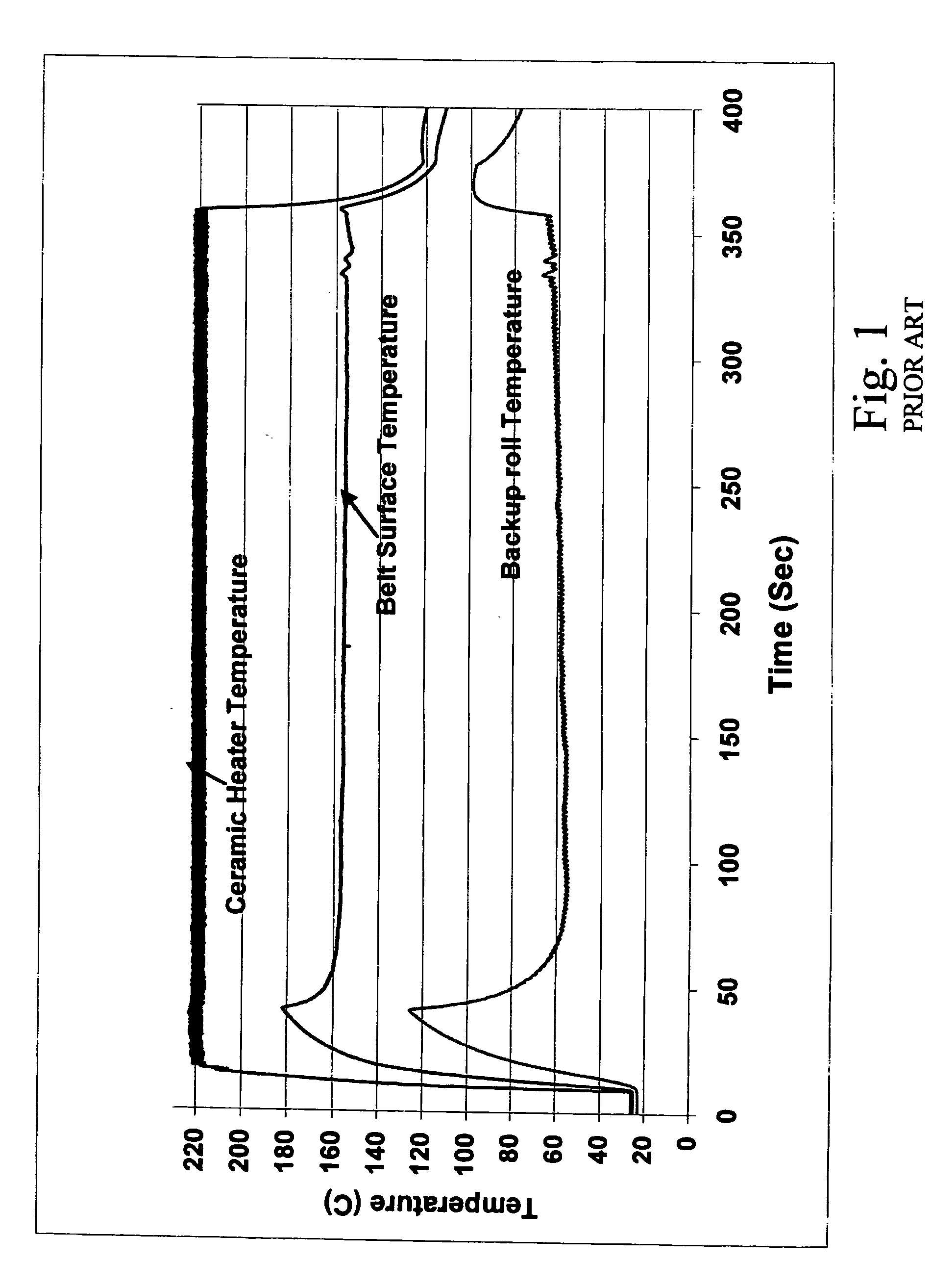
In current belt fusers, when a print job is initiated and the backup roller is cool, the operating temperature is elevated over the normal steady state temperature by as much as 50° C. The excessively high temperatures required for fusing with a cool / cold backup roller can cause the belt to heat to such a temperature that material failure will occur prematurely and the belt will not meet fuser life requirements.
Another point of possible failure is between the PFA sleeve and the base / silicone rubber layer, if such a sleeve is used in the belt construction.
For polyimide belts, material failure occurs in the form of belt buckling or tearing at the edges.

Method used


Image

  • Belt fuser assembly with heated backup roll in an electrophotographic imaging device
  • Belt fuser assembly with heated backup roll in an electrophotographic imaging device
  • Belt fuser assembly with heated backup roll in an electrophotographic imaging device

Examples


Embodiment Construction

[0027] Referring now to the drawings and particularly to FIG. 3, there is shown an embodiment of an EP printer 10 of the present invention. Paper supply tray 12 contains a plurality of print media (not shown), such as paper, transparencies or the like. A print medium transport assembly (not numbered) includes a plurality of rolls and / or transport belts for transporting individual print media through EP printer 10. For example, in the embodiment shown, the print medium transport assembly includes a pick roll 14 and a paper transport belt 16. Pick roll 14 picks an individual print medium from within paper supply tray 12, and the print medium is transported past an intermediate transfer member (ITM) in the form of an ITM belt 18. A plurality of color imaging stations 20, 22, 24 and 26 apply toner particles of a given color to ITM belt 18 at selected pixel locations. The toner particles are then transferred from ITM belt 18 to the print medium in nip 28. In the embodiment shown, color i...


PUM


Abstract

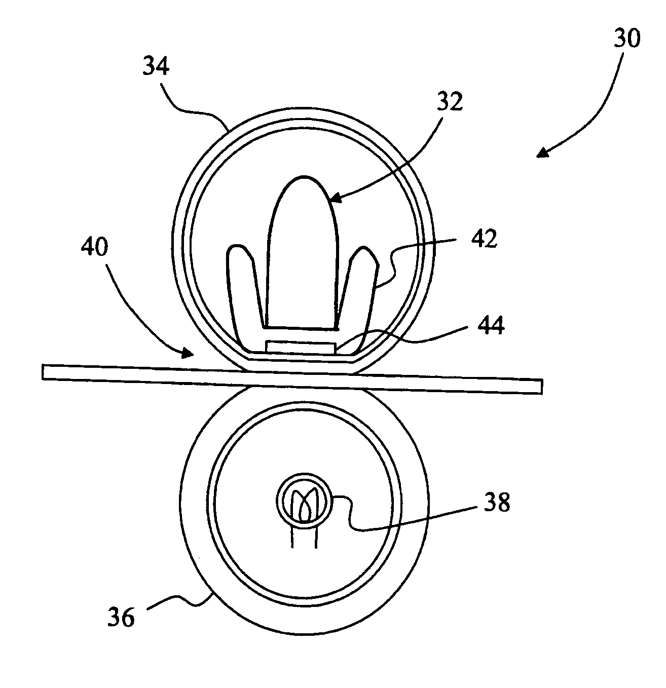
An electrophotographic imaging device includes a print media transport assembly, and a fuser positioned in association with the print media transport assembly. The fuser includes a first heater assembly; a belt positioned around and adjacent to the first heater assembly; a backup roll positioned in opposition to the first heater assembly on a side of the belt opposite the first heater assembly, the belt and the backup roll defining a fusing nip therebetween; and a second heater assembly positioned in association with the backup roll.

Description

BACKGROUND OF THE INVENTION [0001] 1. Field of the Invention [0002] The present invention relates generally to electrophotographic imaging devices and, more particularly, to fusers of electrophotographic imaging devices. [0003] 2. Description of the Related Art [0004] In the electrophotographic (EP) imaging process used in printers, copiers and the like, a photosensitive member, such as a photoconductive drum or belt, is uniformly charged over an outer surface. An electrostatic latent image is formed by selectively exposing the uniformly charged surface of the photosensitive member. Toner particles are applied to the electrostatic latent image, and thereafter the toner image is transferred to the media intended to receive the final permanent image. The toner image is fixed to the media by the application of heat and pressure in a fuser. A fuser may include a heated roll and a backup roll forming a fuser nip through which the media passes. A fuser may also include a fuser belt and an...

Claims


Application Information

Patent Timeline
Patent Type & Authority Applications(United States)
IPC IPC(8): G03G15/20
CPCG03G15/2064G03G2215/2035G03G2215/2016
Inventor CAO, JICHANGGILMORE, JAMES D.
Owner LEXMARK INT INC
Learn More