
High Speed Multi-Mode Receiver

a multi-mode receiver and high-speed technology, applied in the field of data receivers, can solve the problems of insufficient approach for higher transmission rate systems, unreliable wired communications, and obstacles to using fixed-coefficient ffe at transmission rates above about 6 gbs

Active Publication Date: 2006-03-30
MARVELL ASIA PTE LTD
View PDF12 Cites 59 Cited by
  • Summary
  • Abstract
  • Description
  • Claims
  • Application Information

AI Technical Summary

Benefits of technology

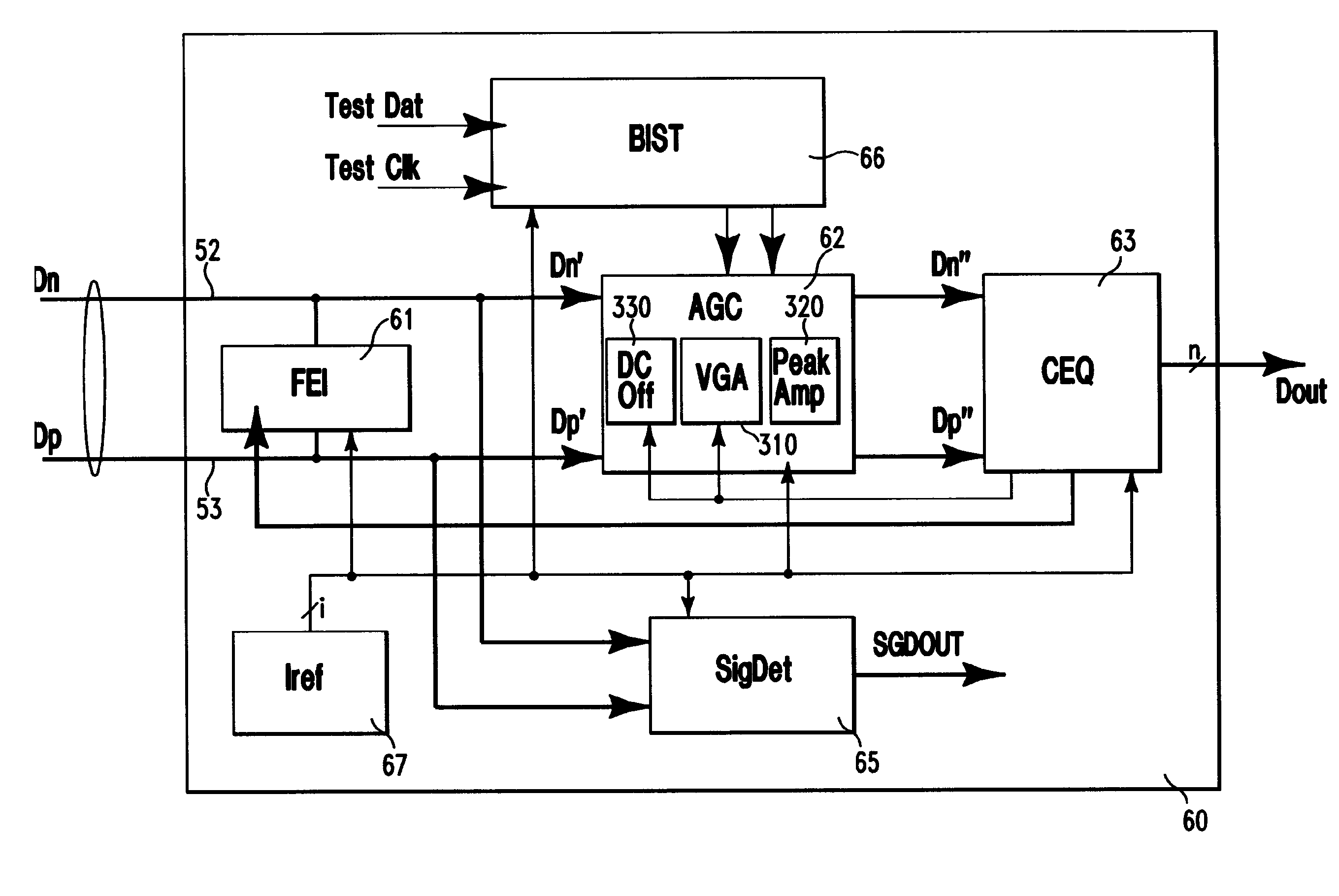
[0017] According to a preferred aspect of the invention, a data receiver is provided which includes an automatic gain control unit including a variable gain amplifier and a peaking amplifier. In a first mode, the variable gain amplifier is operable to amplify a data-carrying signal from a transmitter to a predetermined level and the peaking amplifier is operable to amplify the signal substantially without peaking. In a second mode, the variable gain amplifier is operable to amplify the signal with fixed gain and the peaking amplifier is operable to amplify the signal with peaking.
[0018] In this preferred aspect of the inventio

Problems solved by technology

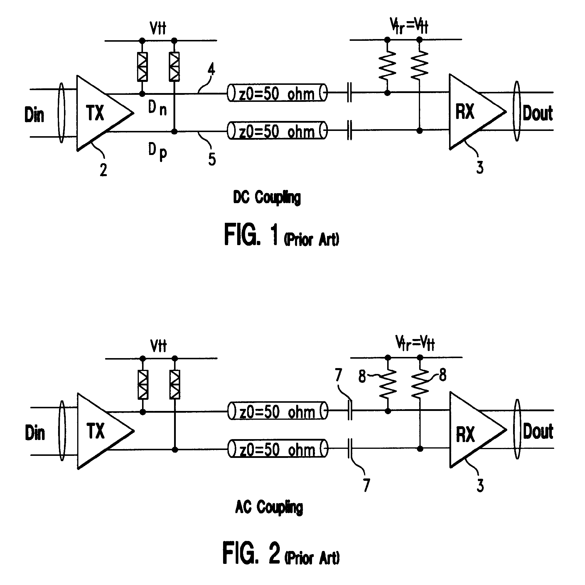
In high-speed data communications, especially those in which data is transmitted serially at rates greater than one gigabit per second (Gbs), wired communications become unreliable unless an equalizer is used to compensate the channel impairments.
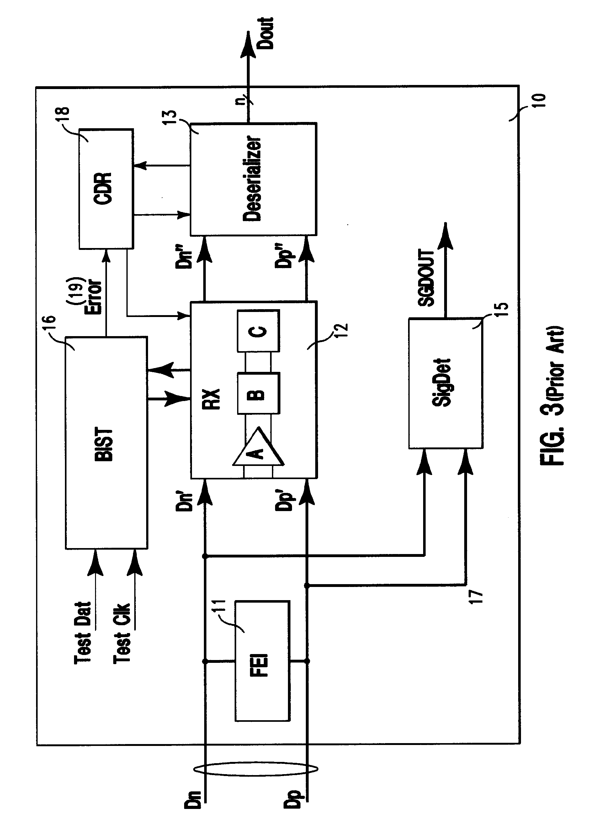
A challenge for high-speed data receivers, especially high-speed serializer-deserializer (SerDes) units, is to simultaneously use both an FFE and a DFE simultaneously, such that the tap coefficients of the equalization devices at both ends of the channel are adjusted for optimal performance.
However, such approach is inadequate for higher transmission rate systems.
A serious obstacle exists to using a fixed-coefficient FFE at transmission rates above about 6 Gbs, due to greater variations in transmission characteristics from one channel to another channel, as well as greater variations in channel distortion.
However, when the common mode level of the arriving signal lies outside the voltage range the receiver is designed to handle, the receiver cannot amplify the signal efficiently, and may recover data poorly.
In other words, the receiver cannot properly decode a signal in which a long consecutive string of “1s” or “0s” appears at the input to the receiver.
Moreover, in systems in which only the data signal is transmitted but not the clock, it is difficult to recover the clock from the transmitted signal when the transmitted signal has long strings of either “1”s or “0”s.
However, a data signal transmitted via an 8b10b code requires 10 signal bits to transfer 8 bits of information, equivalent to 20% of bandwidth loss.
However, heretofore, such flexibility has not been available in prior SerDes communication systems.

Method used


Image

  • High Speed Multi-Mode Receiver
  • High Speed Multi-Mode Receiver
  • High Speed Multi-Mode Receiver

Examples


Embodiment Construction

[0031] Accordingly, in the embodiments of the invention described herein, a robust wire communication system is provided in which tap coefficients of a DFE in the receiver at one end of a transmission channel is updated during normal data transmission operation. In addition, tap coefficients of an FFE at the transmitter at another end of the transmission channel are updated by feedback from the receiver. Such feedback is provided through the transmission channel itself, such as during a test mode. A receiver complex according to an embodiment of the invention includes a central equalization unit operable to generate equalization information for updating the tap coefficients of the DFE at the receiver complex and those of the FFE of the remote transmitter. In a further embodiment described herein, the receiver complex includes an up-channel communication device which transmits the coefficient updating information generated at the receiver complex to the FFE located at the transmitter...


PUM


Abstract

A data receiver is provided which is operable to receive a signal controllably pre-distorted and transmitted by a transmitter, to generate information for adjusting the pre-distortion applied to the signal transmitted by the transmitter, and to transmit the information to the transmitter. The receiver is further operable to perform adaptive equalization to receive the signal transmitted by the transmitter.

Description

BACKGROUND OF THE INVENTION [0001] The present invention relates to data receivers, especially for high-speed wired communications. [0002] In high-speed data communications, especially those in which data is transmitted serially at rates greater than one gigabit per second (Gbs), wired communications become unreliable unless an equalizer is used to compensate the channel impairments. Two common types of equalizers are feed forward equalizers (“FFE”) and decision feedback equalizers (“DFE”). An FFE is used at a transmitter to pre-process the signal being transmitted in a way that compensates for the distorting effects of the transmission channel. In that way, the pre-processed signal arrives at the receiver with lower distortion. An example of an FFE is a multiple-tap finite impulse response (“FIR”) filter. A FIR is a device which digitally processes a serial digital signal for transmission by creating a coefficient-weighted sum of the instant datum of the digital signal together wit...

Claims


Application Information

Patent Timeline
IPC IPC(8): H03K5/01H04B1/10H04L25/08
CPCH03F1/3241H04L25/0278H04L25/0292H04L25/03343H04L2025/03808H04L25/085H04L2025/0349H04L2025/03566H04L2025/03617H04L25/061
Inventor HSU, LOUIS C.JI, BRIAN L.MASON, JAMES S.SELANDER, KARL D.SORNA, MICHAEL A.ZIER, STEVEN J.
Owner MARVELL ASIA PTE LTD
Learn More