Wireless tracking system based upon phase differences

a phase difference and tracking system technology, applied in direction finders, direction finders using radio waves, instruments, etc., can solve the problems of limiting resolution and many deficiencies of this type of system, and achieve the effect of higher accuracy

Inactive Publication Date: 2006-03-30
MIN GUOHUA
View PDF11 Cites 61 Cited by
  • Summary
  • Abstract
  • Description
  • Claims
  • Application Information

AI Technical Summary

Problems solved by technology

Several deficiencies may occur with this type of system.
For one, relying only on the time of arrival of the signal itself, without regard to details of the received signal(s) may limit resolution.

Method used


Image

  • Wireless tracking system based upon phase differences
  • Wireless tracking system based upon phase differences
  • Wireless tracking system based upon phase differences

Examples


Embodiment Construction

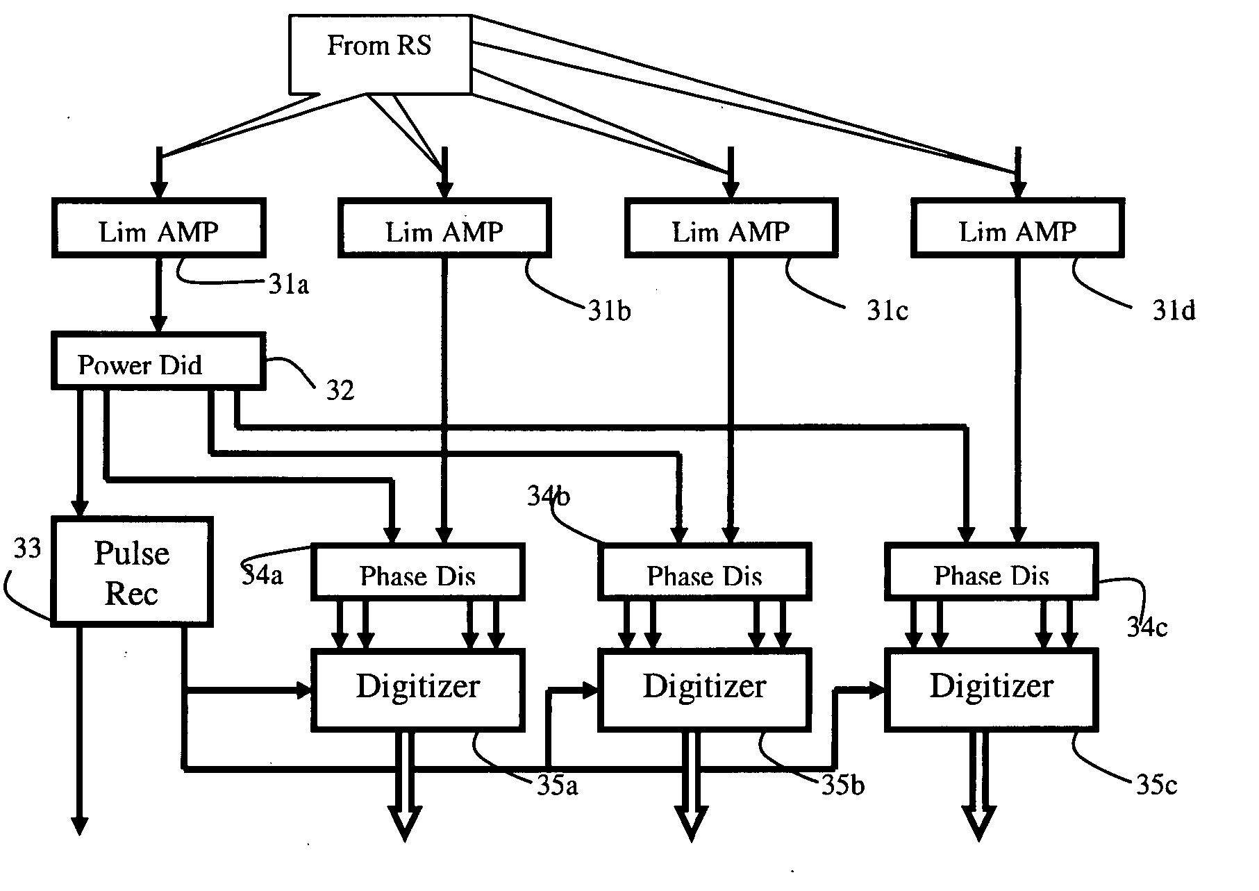
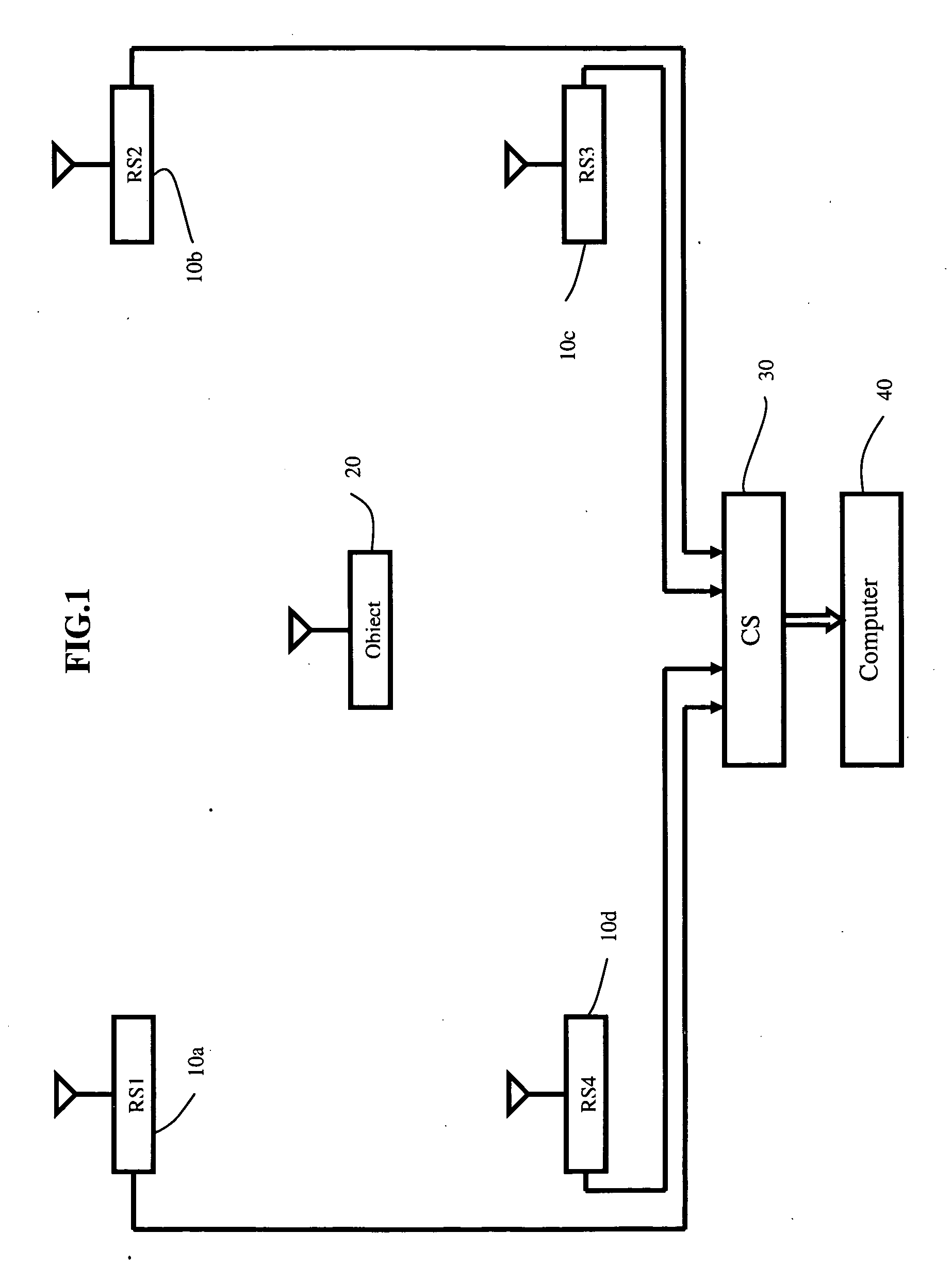
[0019] Referring to FIG. 1, therein is illustrated the millimeter position localizer system that includes a plurality of receiver stations (receivers and / or transceivers) 10a through 10d, a transmitter 20 carried on a stationary or moving object of which position is to be determined, a central station 30 to process the Microwave / RF signals, and a computer 40 which includes an interface circuit to calculate the coordinates of the object.

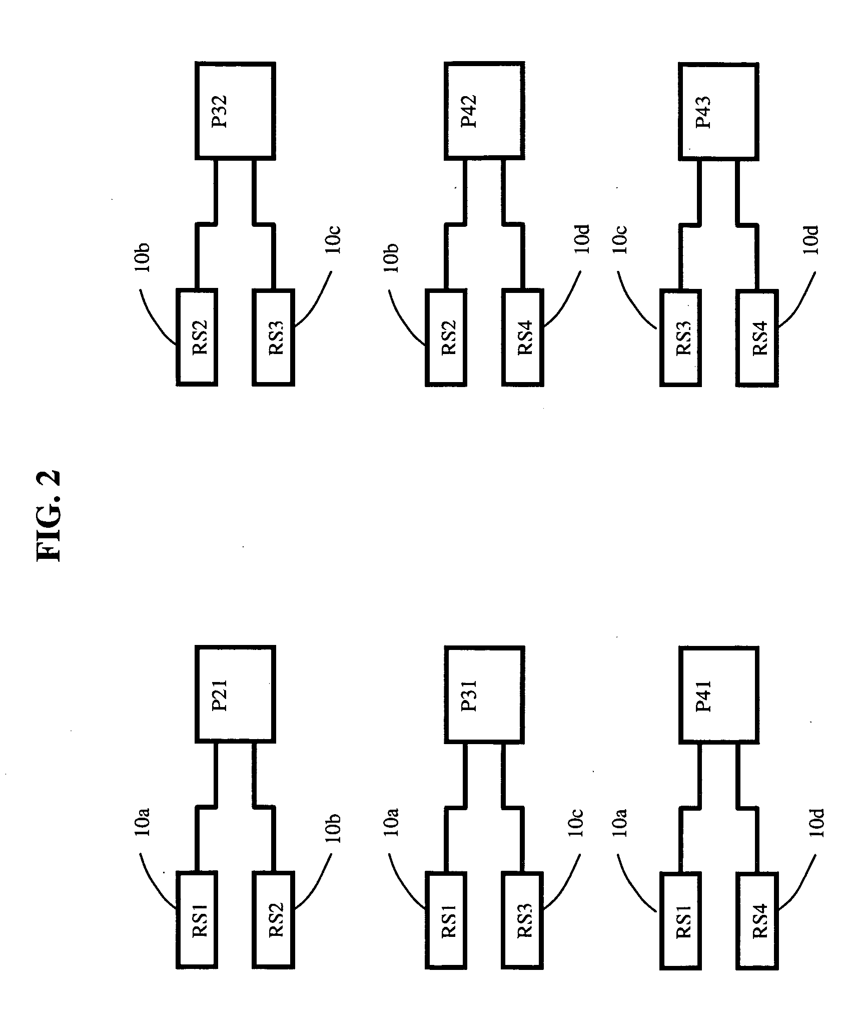
[0020] The receiver stations 10a to 10d form a receiver network and the object carrying a transmitter 20 works within that network's physical layout. The transmitter 20 and the receiver stations 10a through 10d are located within sight of each other. Coordinates of each phase center of receiver stations' antenna(s) will be pre-determined and used as physical references for correlating the transmitter(s)' physical location within the receiver station network. Also, the transmitter(s)' antenna(s)' phase center is used as a reference for the physical po...


PUM


Abstract

A system and method of obtaining high accuracy position information relating to one or more mobile transmitters within a wireless tracking system relies upon phase differences for the time difference of arrival measurements of the transmitter(s). One or more transmitters send signals to multiple receivers, and the time difference of arrival of the transmitter(s) radio signals received at each receiver is used to determine the physical location of the transmitter(s). The high accuracy of the system is obtained through a process of using the transmitter(s)' signals' phase as a reference for time measurements. Since electromagnetic waves travel at the speed of light, knowing how long it takes for a wave to travel from the transmitter to the receiver stations enables a central station to determine the distances the receiver stations are from the transmitter. With predetermined receiver station coordinates, the coordinate of an object embedded with, or carrying, the transmitter can be determined.

Description

REFERENCE TO RELATED APPLICATION [0001] This application claims priority from U.S. Provisional Patent Application Ser. No. 60 / 612,942, filed Sep. 24, 2004, the entire content of which is incorporated herein by reference.FIELD OF THE INVENTION [0002] This invention relates generally to wireless tracking systems and, in particular, to a wireless tracking system that uses phase differences. BACKGROUND OF THE INVENTION [0003] In many applications it is desirable to track, in a non-contact manner, the position of an object as it moves through 3-dimensional space. One method of accomplishing this is to embed an RF transmitter in the object to be tracked. Multiple RF receivers, positioned at known locations, capture the transmitted signal from the object to be tracked. Because the RF energy propagates at a known velocity, the differences in arrival time of the signal at any one pair of the receivers can be used to determine the possible positions of the tracked object in two dimensions. [0...

Claims


Application Information

Patent Timeline
Patent Type & Authority Applications(United States)
IPC IPC(8): G01S3/02
CPCG01S5/06G01S5/0221G01S5/02213
Inventor MIN, GUOHUA
Owner MIN GUOHUA
Why Eureka
Try Eureka