
Radar detection helmet visor

a radar detection and helmet technology, applied in wave based measurement systems, electric devices, instruments, etc., can solve the problems of not being accepted by motorcycle riders, radar detection helmets cannot allow movement of detection mechanisms, and driving tasks that do not allow effective monitoring of visual indicators

Inactive Publication Date: 2006-03-30
ISZLEY HENRY V
View PDF7 Cites 6 Cited by
  • Summary
  • Abstract
  • Description
  • Claims
  • Application Information

AI Technical Summary

Benefits of technology

[0010] The present invention comprises for installation on any helmet. In one presently preferred embodiment, the visor is readily detachable and re-attachable to suitably prepared helmets.
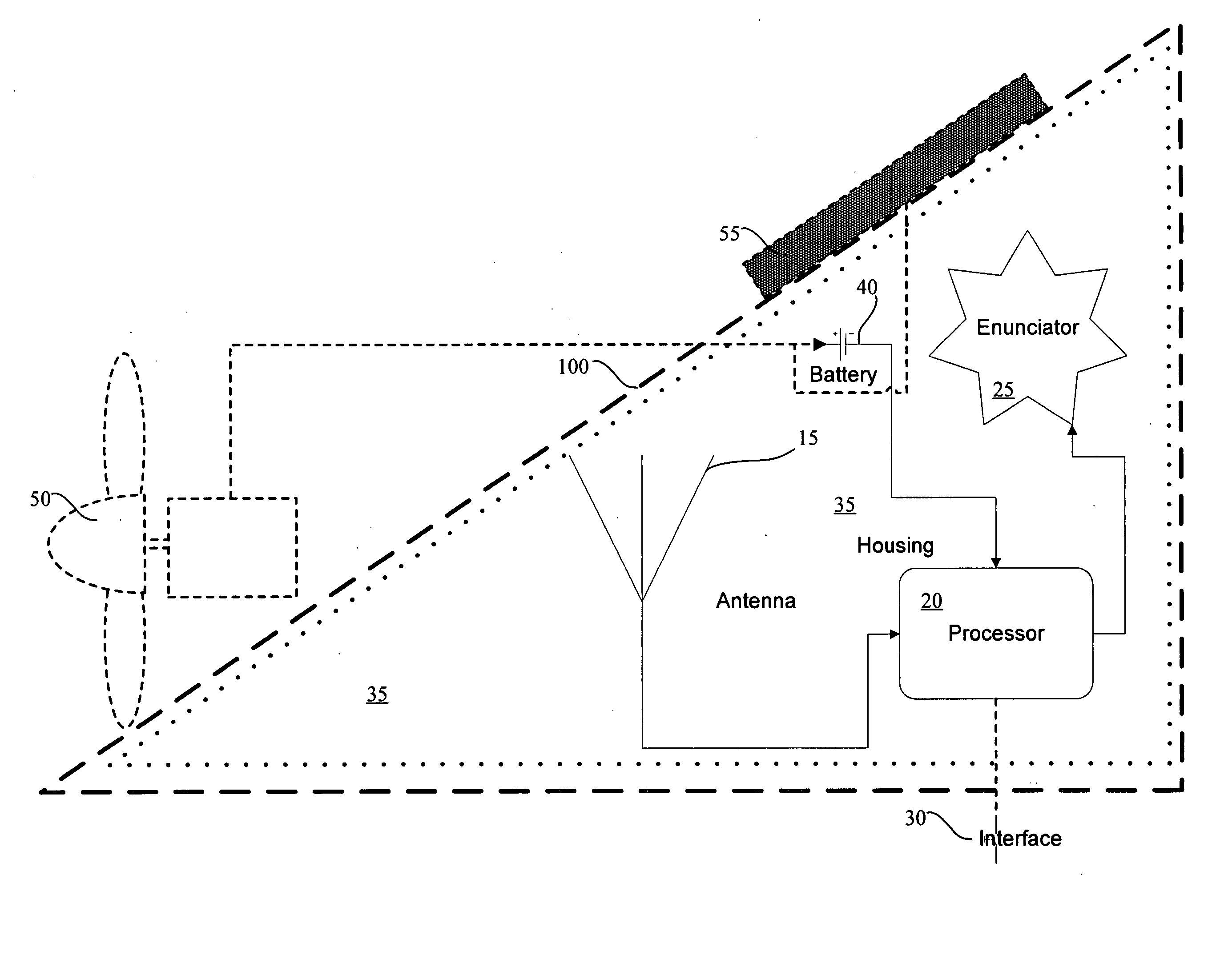
[0013] In accordance with still further aspects of the invention, a GPS system may be suitably included in the visor. Additionally, a timer and clock function are advantageously included either for synchronization to the GPS signal or as stand-alone functions. Audio enunciators for “off-route”“on route”“next turn” or other suitable functions may be included. Visual enunciators may be used for “off-route”“on route”“next turn” or other suitable functions as well as functions suitable to the radar detection function. A screen may be provided for either on-head or off-head use depending upon user preference or safety concerns. Ambient light sensing means may be included to allow suitable attenuation of visual enunciators and screens to prevent distraction from the driving task.

Problems solved by technology

When a radar detector is placed on a motorcycle, ambient noise will often drown out any detection enunciator and the task of driving will not allow for effective monitoring of a visual indicator, the positioning of the radar detector traditionally being in the proximity of handlebars on the radar detector.
For this reason, conventional radar detectors configured for use in an automobile or truck have not gained acceptance among motorcycle ridership.
Unfortunately, the radar detection helmet will not allow movement of the detection mechanism from one helmet to another helmet.

Method used


Image

  • Radar detection helmet visor
  • Radar detection helmet visor
  • Radar detection helmet visor

Examples


Embodiment Construction

[0025] A radar detection device, radar detection device container, and a method includes a housing configured to attach to a motorcycle helmet to shield eyes of a motorcycle helmet wearer from overhead sunshine. The housing defines a void configured to house a radar detection circuit. The circuit is configured to reside in the void and includes an antenna. The antenna is configured to receive an electromagnetic signal. The electromagnetic signal is one of the group consisting of radar signals having wavelengths in the X-band, K-band and Ka-Band and lidar signals and to generate an operative signal based upon receipt of the electromagnetic signal. A processor is configured to receive the operative signal from the antenna according to the electromagnetic signal received at the antenna.

[0026] Referring to FIG. 1, a radar detection device visor includes a housing 10 configured to attach to a motorcycle helmet to shield eyes of a motorcycle helmet wearer from overhead sunshine and defin...


PUM


Abstract

A radar detection device, radar detection device container, and a method includes a housing configured to attach to a motorcycle helmet to shield eyes of a motorcycle helmet wearer from overhead sunshine. The housing defines a void configured to house a radar detection circuit. The circuit is configured to reside in the void and includes an antenna. The antenna is configured to receive an electromagnetic signal. The electromagnetic signal is one of the group consisting of radar signals having wavelengths in the X-band, K-band and Ka-Band and lidar signals and to generate an operative signal based upon receipt of the electromagnetic signal. A processor is configured to receive the operative signal from the antenna according to the electromagnetic signal received at the antenna.

Description

FIELD OF THE INVENTION [0001] The field of invention relates to radar detector apparatus, and more particularly pertains to a radar detection helmet visor. BACKGROUND OF THE INVENTION [0002] Radar is still the most popular form of speed detection—some 100,000 guns are in use, and roughly 20,000 new ones are sold each year. A radar gun works by transmitting a microwave beam at the vehicle from which a speed is to be determined. When that beam reflects off the moving vehicle, the microwave beam changes is frequency due to Doppler shifting, and the reflected frequency is used to calculate speed. [0003] Traffic radar, which is regulated by the Federal Communications Commission (FCC), operates on three frequency ranges. The oldest is X-band, from 10.500 to 10.550 gigahertz (GHz); about 10 percent of all radar guns use this band. The most popular radar representing about 60 percent of guns, operates on K-band, at 24.050 to 24.250 GHz. Increasingly popular is Ka-band, which spans a wide ra...

Claims


Application Information

Patent Timeline
Patent Type & Authority Applications(United States)
IPC IPC(8): G01S7/40
CPCG01S7/022
Inventor ISZLEY, HENRY V.
Owner ISZLEY HENRY V
Learn More