Magnetic resonance detector and method

a magnetic resonance and detector technology, applied in the field of magnetic resonance systems and methods, can solve the problems of increasing the number of mr detectors in the mr system, increasing the number of conductive cables, and corresponding increase of conductive cables,

Active Publication Date: 2006-03-30
GENERAL ELECTRIC CO
View PDF18 Cites 6 Cited by
  • Summary
  • Abstract
  • Description
  • Claims
  • Application Information

AI Technical Summary

Problems solved by technology

One problem with increasing the number of MR detectors in the MR system is corresponding increase of conductive cables.
Conductive cables can be bulky, stiff and hard to mechanically manipulate.
In addition, they can also create radio frequency loops that could potentially cause a burn to be induced in the imaging subject.
Furthermore, conductive cables and the conductive shields used on the conductive cables tend to pick up transient or interference signals and couple them into the MR detector array causing an image artifact and image degradation.
Another problem when increasing the number of MR detectors is the corresponding increase in space required to install the MR detectors and the conductive cables.
Also, implementation of such systems contributes to an overall increase in the cost of the system.

Method used


Image

  • Magnetic resonance detector and method
  • Magnetic resonance detector and method
  • Magnetic resonance detector and method

Examples


Embodiment Construction

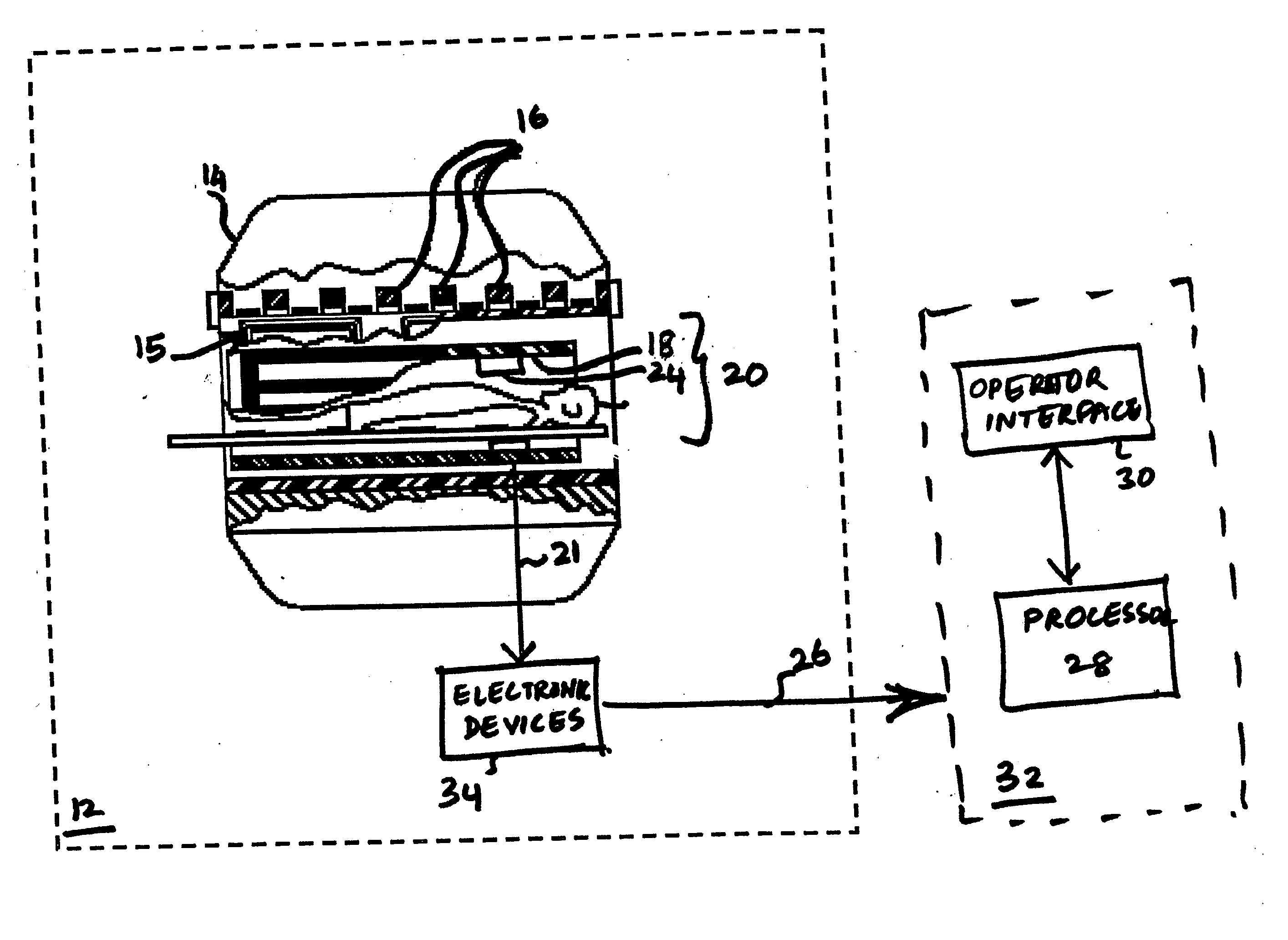
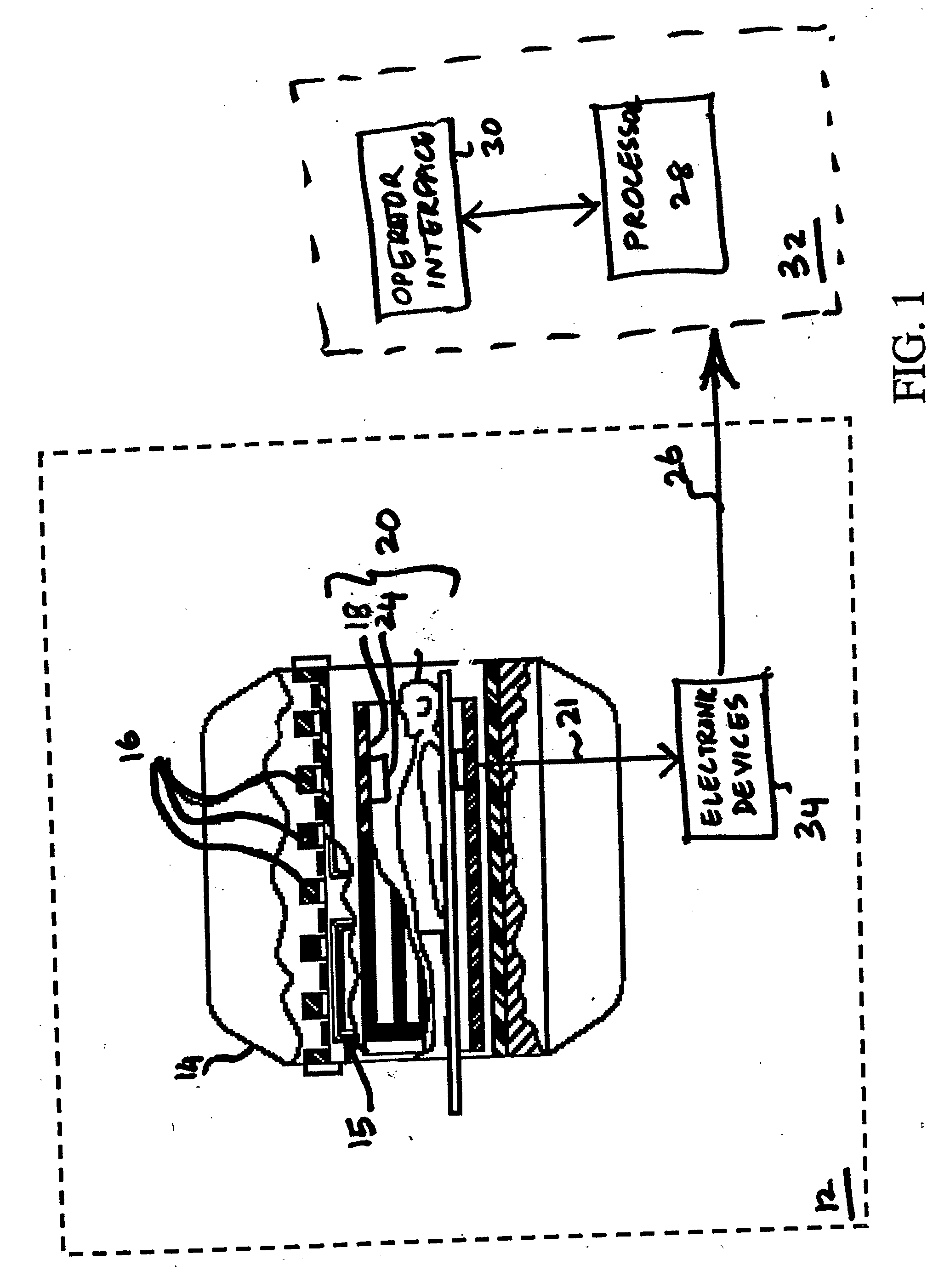
[0016]FIG. 1 is a block diagram of an exemplary embodiment of a high field magnetic resonance (MRI) system 10 which may be use in accordance with aspects of the invention. Other magnetic resonance systems such as magnetic resonance spectroscopy systems, which can be used to analyze material properties may also benefit from the present techniques. The following discussion of an MRI system is merely an example of one such implementation and is not intended to be limiting in terms of modality or anatomy.

[0017] As used herein, the term “high field” refers to magnetic fields produced by the MRI system that is greater than about 0.5 Tesla. For embodiments of the invention the high field is desirably 0.5 Tesla to 7 Tesla. The MRI system could be, for example, a GE-Signa MR scanner available from GE Medical Systems, Inc., which is adapted to perform the method of the present invention, although other systems could be used as well. Each component is described in further detail below.

[0018]...


PUM


Abstract

A magnetic resonance (MR) system and method for generating information about an object is provided. The MR system comprises at least one MR detector configured to sense a plurality of signals within a shielded environment and a digitizing circuit configured for digitizing the analog signals to generate digital signals. The MR detector, digitizing circuit is located within a shielded environment. The system further comprises a first transmission element configured for transmitting the plurality of digital signals to a plurality of electronic devices.

Description

BACKGROUND [0001] The invention relates generally to imaging and spectroscopy systems and more specifically to magnetic resonance systems and methods. [0002] High field magnetic systems such as magnetic resonance (MR) systems are typically located inside a shielded environment. The shielded environment is where a magnet bore of a magnetic resonance system is located. Typically, a magnetic resonance detector is used to detect electromagnetic signals carrying information about the object being imaged. The electromagnetic signals are then amplified and transmitted to an operator console located outside the shielded environment for further processing. [0003] Several MR detectors are used as sensing elements in MRI systems and are used for sensing and transmitting electromagnetic signals. MR detectors may include receive coils such as radio frequency coil, surface coils and surface coil arrays. To increase the quality of the images, or extend field of view, or imaging speed, MRI systems ...

Claims


Application Information

Patent Timeline
IPC IPC(8): G01V3/00
CPCG01R33/283G01R33/3692G01R33/3621
Inventor WATKINS, RONALD DEANFREY, RICHARD LOUISKOSTE, GLEN PETERCHANDRA, NAVEEN STEPHAN
Owner GENERAL ELECTRIC CO
Why Eureka
Try Eureka