
Gimbaled mounting bracket

a mounting bracket and gimbal technology, applied in the direction of washing stands, machine supports, building scaffolds, etc., can solve the problems of difficult to achieve precise alignment, difficult to precisely adjust the opening of the small orifice, and inconvenient installation, so as to reduce stress and wear on the actuator shaft, reduce the effect of alignment and fast installation

Active Publication Date: 2006-03-30
VOONER FLOGARD CORP
View PDF11 Cites 22 Cited by
  • Summary
  • Abstract
  • Description
  • Claims
  • Application Information

AI Technical Summary

Benefits of technology

[0015] Accordingly, it is an object of the current invention to provide a mounting method for a shower actuator that would provide easy alignment of the actuator with the shower piping.
[0016] It is another object of the invention to provide a mounting bracket that is capable of easily aligning a shower actuator with a plumbing apparatus.
[0017] It is another object of the invention to provide a mounting bracket that is capable of automatic or self-angular adjustment of a mounted shower actuator in order to eliminate stresses that would otherwise be applied to the actuator ram. SUMMARY OF THE INVENTION
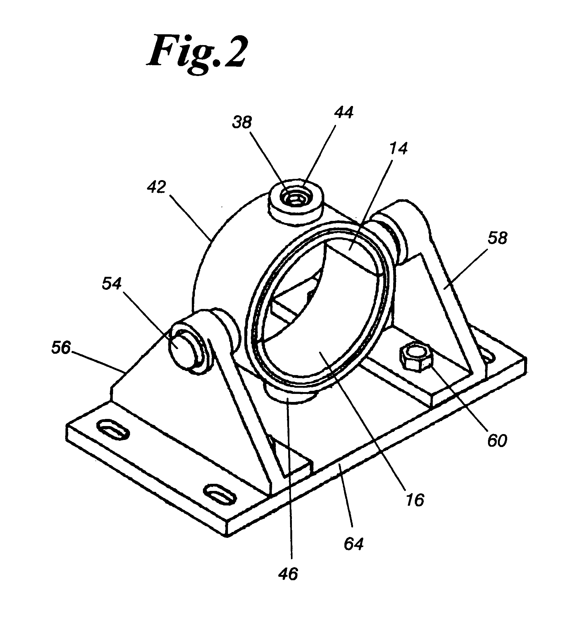
[0019] The actuator gimbal mount provides total freedom of movement, allowing the actuator shaft connector to follow the travel of the shower connector in any direction required by the installed shower centerline. This freedom of movement allows for faster installation, minimal alignment, and reduces stress and wear on the actuator shaft.
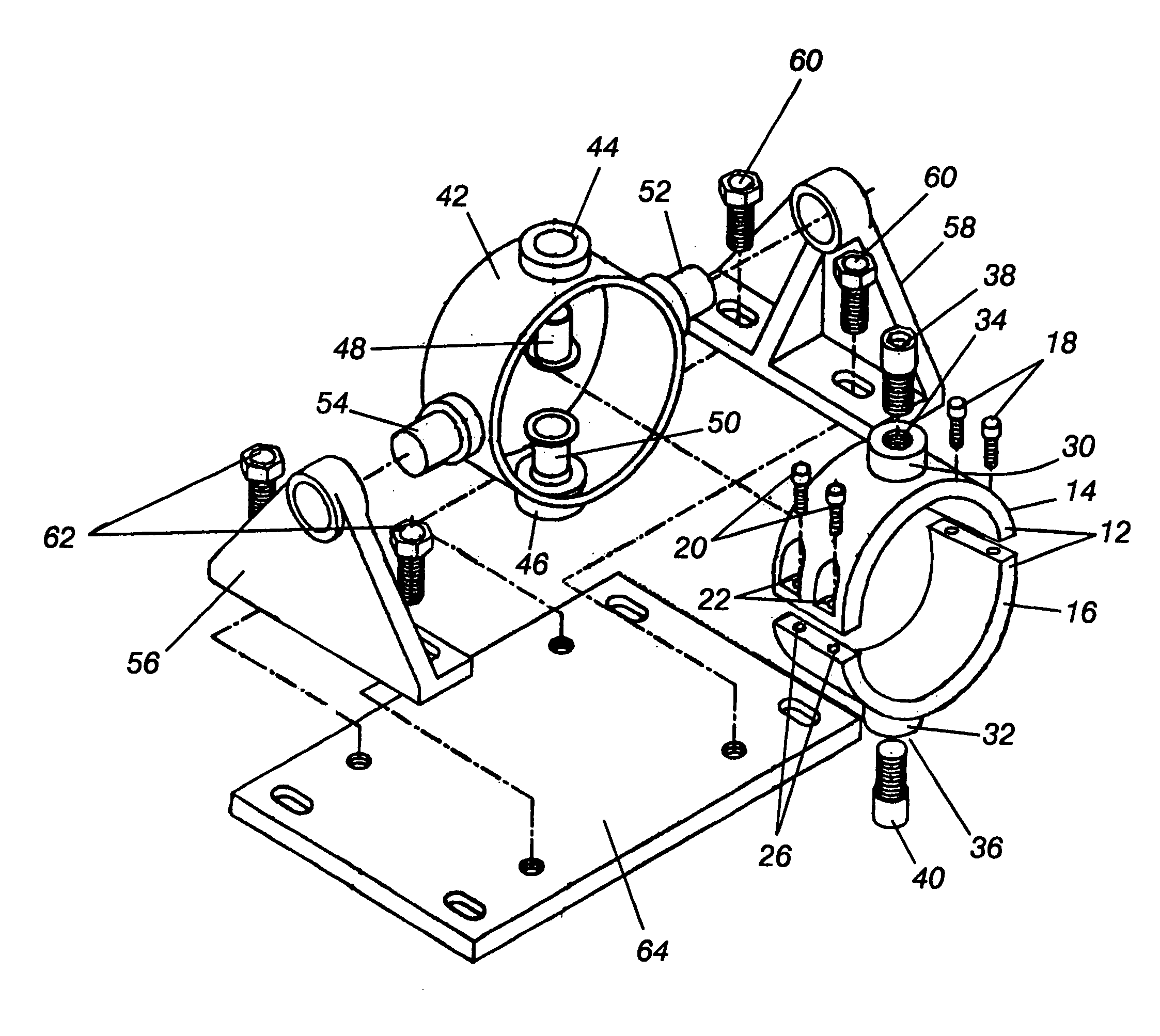
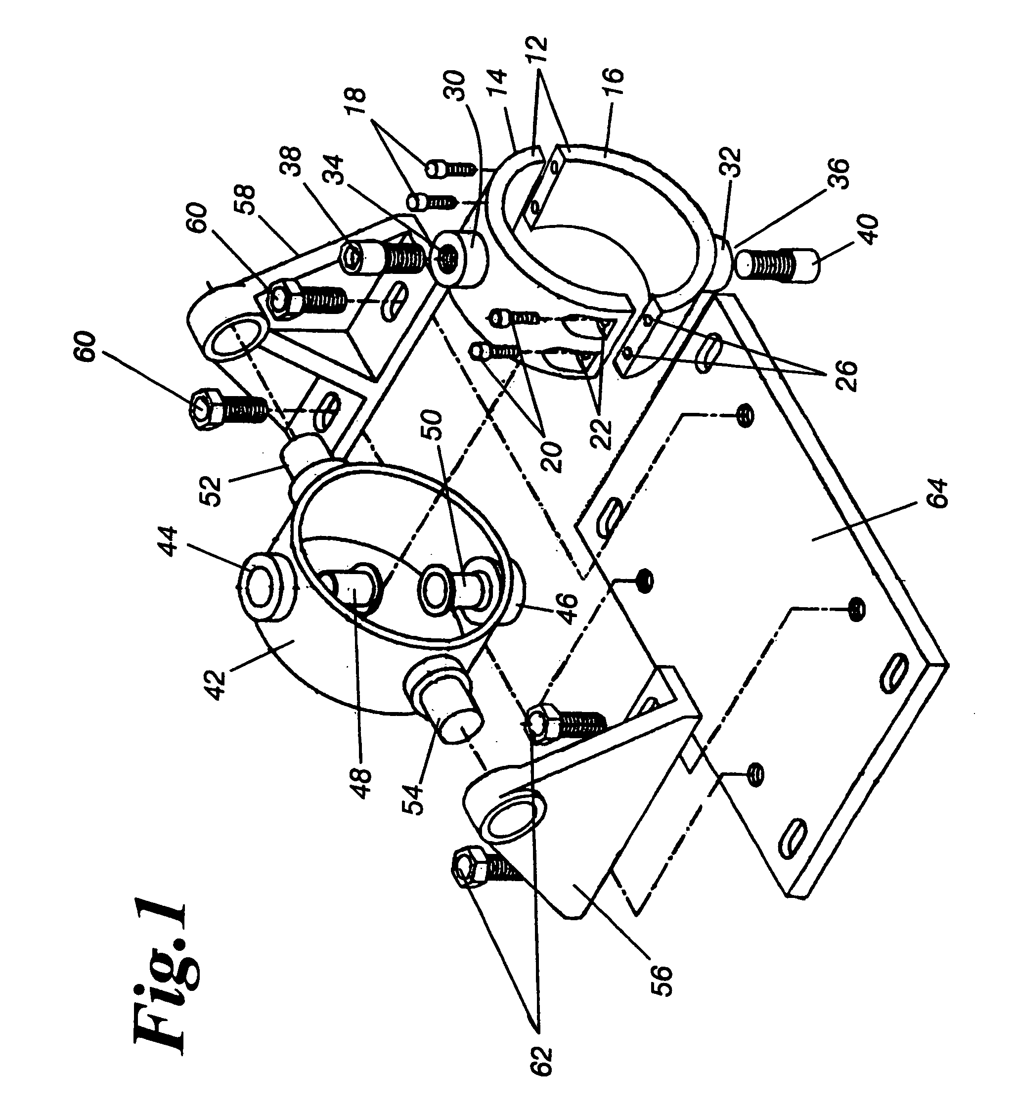
[0020] The actuator gimbaled mount consists of two concentric rings, one of which is attached to the outside diameter of the actuator ram housing. This inner mounting ring has two vertical mounting pivot pins, one at the top and one at the bottom, which fit into the bearing bosses on the outer pivot ring. The outer ring has two horizontal pivot pins, one on the left and one on the right. These pins fit into trunnions mounted to the frame that supports the actuator on the machine it is to be used on. The gimbal mount allows freedom of movement eliminating harmful loads that would otherwise be applied to the actuator ram.

Problems solved by technology

Adding water to the paper appears to be counterproductive, as the final purpose of the paper machine is to control the moisture to a relatively low level, typically 5% to 10%.
It can be appreciated that precisely adjusting the opening of the small orifice is very difficult.
Achieving this precise alignment is tedious, difficult, and time consuming.

Method used


Image

  • Gimbaled mounting bracket
  • Gimbaled mounting bracket
  • Gimbaled mounting bracket

Examples


Embodiment Construction

[0025]FIG. 1 shows an exploded view of the isometric view of the gimbaled mounting device 10.

[0026] A mounting ring 12 is provided to secure a shower actuator to the mounting device. The mounting ring's inside diameter is preferably equal to or slightly less than the outside diameter of the shower actuator so that the actuator is securely held within the mounting ring 12. A mounting ring having a larger diameter could be utilized, although this is not preferred.

[0027] The mounting ring 12 is itself comprised of at least one upper crescent member 14, and one lower crescent member 16. It is preferable that each of the crescent members has an arcuate length of less than ½ the total circumference of the mounting ring 12. Arcuate lengths of less than ½ of mounting ring's circumference are preferred in order to facilitate attaching the mounting ring 12 to the shower actuator without damage to the crescent members or the shower actuator. An arcuate length of greater than ½ of the mountin...


PUM


Abstract

A gimbaled mounting bracket apparatus for aligning an actuator with a receptacle is disclosed, having a mounting ring rotatable around a pair of gudgeons. A concentric rotation ring attached to the pair of gudgeons. The concentric ring is mounted to a base along a rotational axis orthogonal to the gudgeons. The mounting ring retains a shower actuator that is to be aligned with a piping apparatus. The shower actuator can be angularly adjusted relative to piping apparatus to produce a collinear relationship, but is free of any translational movement relative to said receptacle, so as to minimize stresses exerted on said actuator.

Description

FIELD OF THE INVENTION [0001] This invention relates to alignment positioning mechanisms and devices. More particularly, this invention relates to a mechanism for compensating a misalignment between two structurally attached or integrated collinear members. The invention further relates to brackets having angle adjustable mounting centerlines. The invention further relates to adjustably aligning brackets used to compensate or correct for small angular discrepancies between a bracket-mounted object, and a desired collinear receiver for the object. DESCRIPTION OF THE PRIOR ART [0002] Showers are used at various stages in the papermaking process; for example, to clean and / or recondition conveying surfaces and to clean filters that are used for treating wastewater. A shower fitting commonly used in the paper-making industry comprises a hollow shower pipe, which is closed or restricted at one end, and connected at the other end to a source of cleaning / reconditioning fluid (usually water)...

Claims


Application Information

Patent Timeline
IPC IPC(8): G11B5/55D21F1/34F16L3/16
CPCF16L3/16D21F1/34F16C11/06D21F7/008D21G7/00D21H23/50F16D3/38
Inventor ANDERSON, CARL JOHN II
Owner VOONER FLOGARD CORP
Learn More