Intake system including a resonance chamber

Inactive Publication Date: 2006-03-30
HONDA MOTOR CO LTD
View PDF5 Cites 3 Cited by
  • Summary
  • Abstract
  • Description
  • Claims
  • Application Information

AI Technical Summary

Benefits of technology

[0006] A second object of the present invention is to provide such an intake system which is capable of continuously tuning the resonance chamber to the operating condition of the engine such as the engine rotational speed.
[0007] A third object of the present invention is to provide such an intake system which can achieve both resonance supercharging and inertia supercharging by using a highly compact structure.
[0009] According to this arrangement, the configuration of the intake system can be changed so as to obtain the resonance effect over a wide operating range without changing the outer profile of the intake system. Because the inner tube or outer tube defining the communication passage has a relative small mass of inertia as compared with the casing for the resonance chamber, the actuator may consist of a highly compact actuator such as an electric motor which requires very little power consumption, and a favorable responsiveness and controllability can be achieved without any difficulty.
[0010] According to a certain aspect of the present invention, the power actuator turns at least one of the inner and outer tubes relative to each other in a direction to decrease the distance between the communication inlet port and communication outlet port as the rotational speed of the engine increases. Decreasing the distance has the effect of raising the resonance frequency of the resonance chamber.
[0013] According to a preferred embodiment of the present invention, the intake efficiency can be further improved if the resonance supercharging produced by the resonance chamber is combined with the inertia supercharging making use of the inertia of the intake flow. It can be accomplished if the intake passage includes a short intake passage and a long intake passage that are arranged parallel to each other, the intake system further comprising a valve for selectively closing the short intake passage and an actuator for actuating the valve in synchronism with the at least one of the outer and inner tubes that is actuated by the corresponding power actuator.
[0016] For both compact design and easy servicing, the actuator for at least one of the outer and inner tubes may be provided externally of the intake manifold main body.

Problems solved by technology

However, according to the first example of the prior art, because the configuration of the intake system can be changed only in a stepwise fashion for maintaining the resonance effect in relation with the changing operating condition, it is not suitable for use as an intake system for an automotive engine whose operating condition changes continually.
However, the need for the mechanism for moving the resonance chamber creates various problems.
First of all, because the resonance chamber has a significant volume, moving the resonance chamber in dependence on the rotational speed of the engine causes a significant change in the outer profile of the intake system, and this makes it highly difficult to install the engine in a limited space of the engine room of an automobile.
Also, the casing for the resonance chamber is inevitably heavy in weight owing to the size requirement of the resonance chamber, and the mechanism for moving the resonance chamber casing is required to be correspondingly powerful.
This results in a relatively massive actuator and a large consumption of energy.
Also, the large mass of the resonance chamber casing prevents a prompt movement of the resonance chamber casing and this impairs the responsiveness and controllability of the intake system.

Method used


Image

  • Intake system including a resonance chamber
  • Intake system including a resonance chamber
  • Intake system including a resonance chamber

Examples


Embodiment Construction

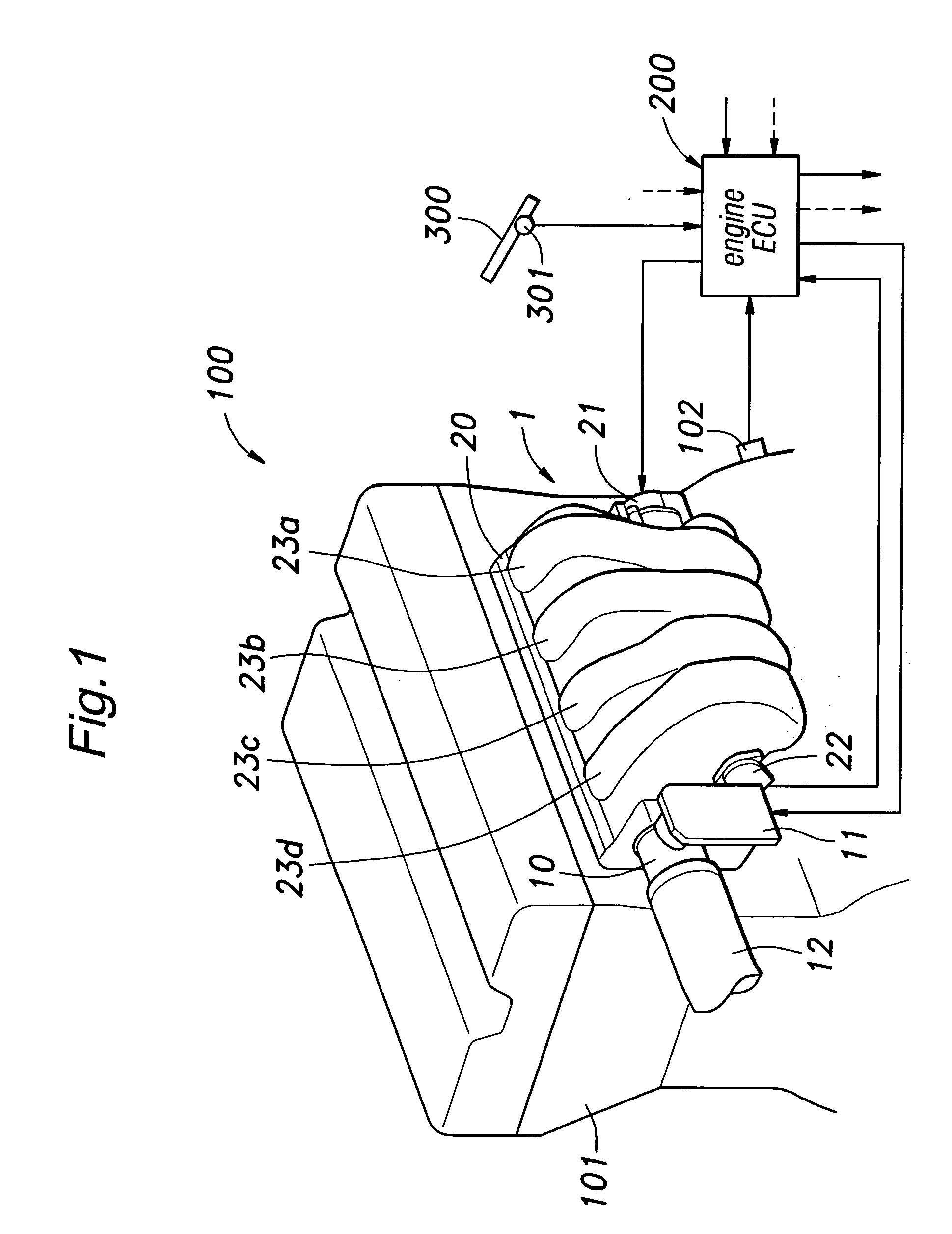
[0031] FIGS. 1 to 10 show a first embodiment of the present invention. FIG. 1 shows an automotive four-stroke in-line multi-cylinder gasoline engine 100, and an intake system 1 embodying the present invention is attached to the cylinder head 101 of this engine. The intake system 1 comprises an electronically controlled throttle unit 10 and an intake manifold 20. The throttle unit 10 is externally provided with a throttle actuator 11. The intake manifold 20 is externally provided with a variable intake passage actuator 21 including an electric motor and a communication sensor 22 which is described hereinafter. The throttle actuator 11 and variable intake passage actuator 21 each include an electric motor, a gear reduction mechanism and a casing. The throttle unit 10 is connected to an intake duct 12 which is in turn connected to an air cleaner not shown in the drawings.

[0032] The throttle actuator 11, variable intake passage actuator 21 and communication sensor 22 are connected to a...


PUM


Abstract

In an intake system for an engine incorporated with a resonance chamber (32), a variable communication unit (50) for controlling the communication between an intake passage with the resonance chamber comprises an outer tube (51) having an open axial end (51a) and an opening (51b) defined in a circumferential wall thereof for communication with the resonance chamber and an inner tube (52) rotatably and coaxially received in the outer tube, the inner tube being provided with a communication inlet port (52a) at an axial end on a same side as the axial end of the outer tube and an opening (52b) in a circumferential wall thereof for defining a communication outlet port (50a) jointly with the opening in the outer circumferential wall of the outer tube. The openings of the inner tube and outer tube are configured such that at least one of a distance (L) between the inlet and outlet ports of the communication passage and an opening area (S) of the communication outlet port changes in relation with a relative rotational angle between the inner tube and outer tube. Thereby, the intake system can be formed as a highly compact unit and requires little power to operate.

Description

TECHNICAL FIELD [0001] The present invention relates to an intake system for internal combustion engines, and in particular to an intake system including a resonance chamber for achieving a favorable intake efficiency over a wide operating range by taking advantage of a resonance effect. BACKGROUND OF THE INVENTION [0002] For the purpose of increasing the output torque of an internal combustion engine, it is desirable to increase the intake efficiency (volumetric efficiency) which is given by dividing the amount of intake air (mixture or air) which is drawn into the combustion chamber during the downward stroke of the piston by the volume of the cylinder. In the field of internal combustion engines, it has been practiced to experimentally determine the volume of a surge tank and / or the length of each independent intake passage of the intake system to maximize the effect of inertia supercharging that makes use of the inertia of the intake flow. It is also known to provide a resonance...

Claims


Application Information

Patent Timeline
IPC IPC(8): F02D9/10F02D11/10F02M35/10
CPCF02B27/0284Y02T10/146F02D11/10F02B27/0215F02B27/0263F02B27/0273Y02T10/12
Inventor AKIMA, KAZUHIROUMINO, YOSHIYUKI
Owner HONDA MOTOR CO LTD
Why Eureka
Try Eureka