
Sensor arrays based on electronic oscillators

a sensor array and electronic oscillator technology, applied in the direction of heat measurement, simultaneous indication of multiple variables, instruments, etc., can solve the problems of engine manufacturing, assembly and disassembly costs, and test cell operation costs,

Inactive Publication Date: 2006-03-30
SCOPRA SCI & GENIE SEC
View PDF4 Cites 5 Cited by
  • Summary
  • Abstract
  • Description
  • Claims
  • Application Information

AI Technical Summary

Benefits of technology

[0009] The foregoing and other objects, advantages and features of the present invention will become more apparent upon reading of the following non restrictive description of an illustrative embodiment thereof, given by way of example only with reference to the accompanying drawings.

Problems solved by technology

It is well recognized that development work spreads over the useful life of an engine, as some unexpected durability problems, often related to cyclic operation, arise only on aircraft wings.
Indeed, since engines are currently designed with safety margins, to ensure durability in all conditions, some engines are not operated to the full capabilities of their components.
Furthermore, ground tests are expensive, accounting for engine manufacturing, assembly and disassembly costs, and test cell operation costs.
In instrumenting low access components such as the high pressure turbine of an aircraft engine, lead routing represents a considerable problem, with conventional sensing technology.
This leads to overcrowding of communication lines in low access locations, and requires a large number of data transfer slip-rings when monitoring rotating parts.
The gas turbine engine optimization process requires considerable ground testing and flight experience, and despite all efforts still carries considerable safety margins.

Method used


Image

  • Sensor arrays based on electronic oscillators
  • Sensor arrays based on electronic oscillators
  • Sensor arrays based on electronic oscillators

Examples


specific example

Integrated Circuit Development

[0067] In order to obtain the full advantages of the sensitive wire 100 shown in FIG. 1, the feedback network 152, amplifier 154 and limiter 156 components of FIG. 3 need to be miniaturized into an integrated circuit such as, for example, the temperature sensitive integrated circuit phase-shift oscillator 510 shown in FIG. 10. It is to be noted that the oscillator 510 is an illustrative example only.

Feedback Network

[0068] As discussed previously, many types of feedback networks may be designed to be sensitive to many different machine parameters, such as, for example, temperature, pressure, strain, vibrations, airflows, etc. Referring to FIG. 10, The temperature sensitive integrated circuit phase-shift oscillator 510 will be described. The oscillator 510 includes a temperature sensitive feedback network 512 using platinum resistors 5221, 5222, 5223, 5224. It is the feedback network 212 of a phase-shift oscillator 210, as shown in FIG. 5, and it cons...

example

[0109] Referring to FIG. 15, as a practical example of a sensor array 630 according to the illustrative embodiment of the present invention, in which two high temperature macroscopic oscillators 610 and 620 are connected so as to provide a multiplexed signal. The oscillators 610, 620 were built and operated in a high temperature environment, and as such high temperature discrete components were assembled on two separate ceramic substrates. The circuits were made to be sensitive to temperature, using platinum resistors in the feedback networks 612, 622.

[0110] RF high power SiC MESFETs from Cree Inc. were used for amplifying. Those transistors providing relatively low transconductance at low power, the Wien bridge configuration 410, presented in FIG. 7, was selected for the oscillators 610, 620, because it allows for low gain amplifier stages. For oscillator 610, the Wien bridge feedback network 612 uses 1500Ω resistors 712 (actually a 1000Ω and a 500Ω connected in series) and 600 pF...


PUM

PropertyMeasurementUnit
frequencyaaaaaaaaaa
thicknessaaaaaaaaaa
thicknessaaaaaaaaaa

Abstract

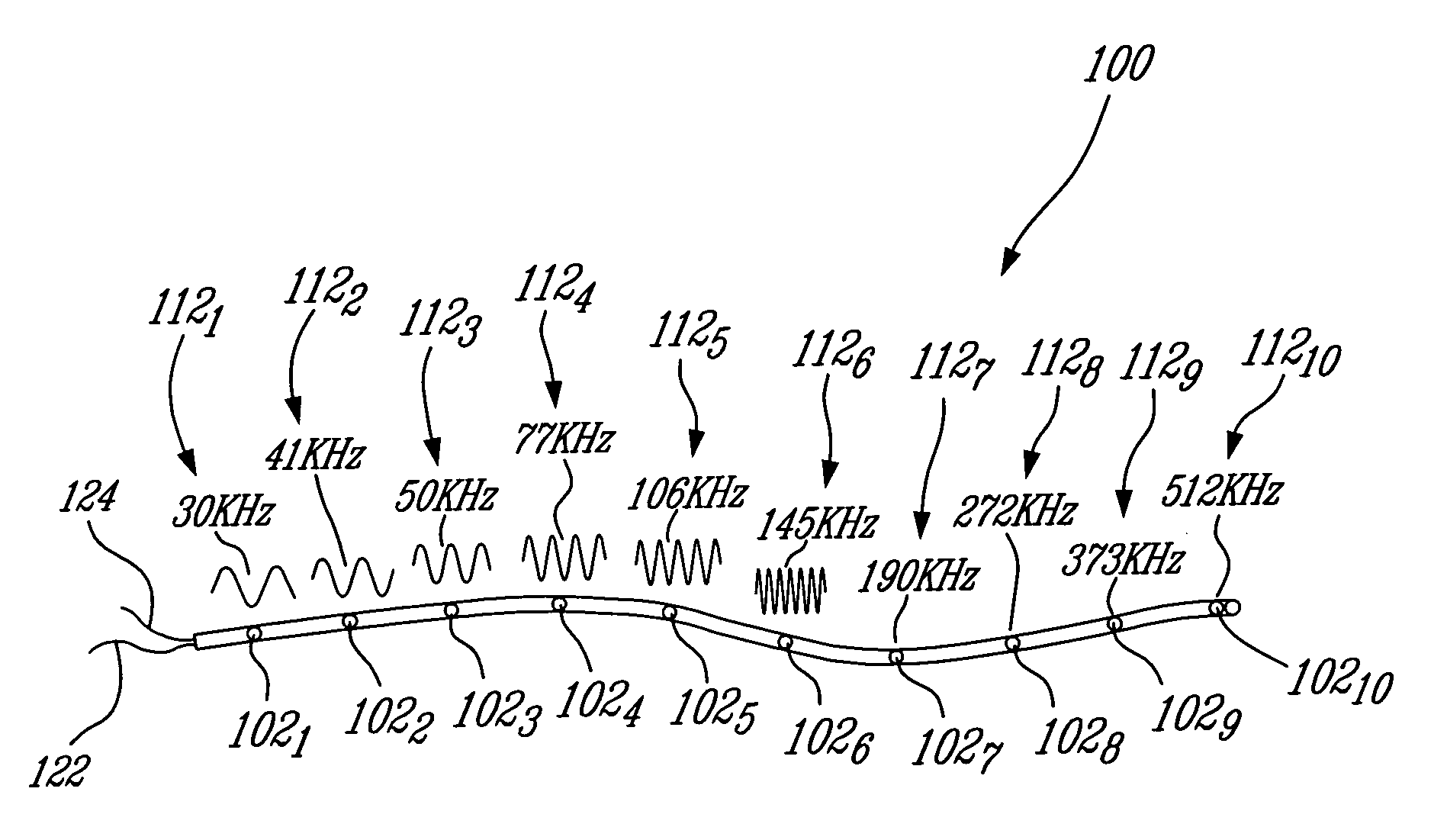
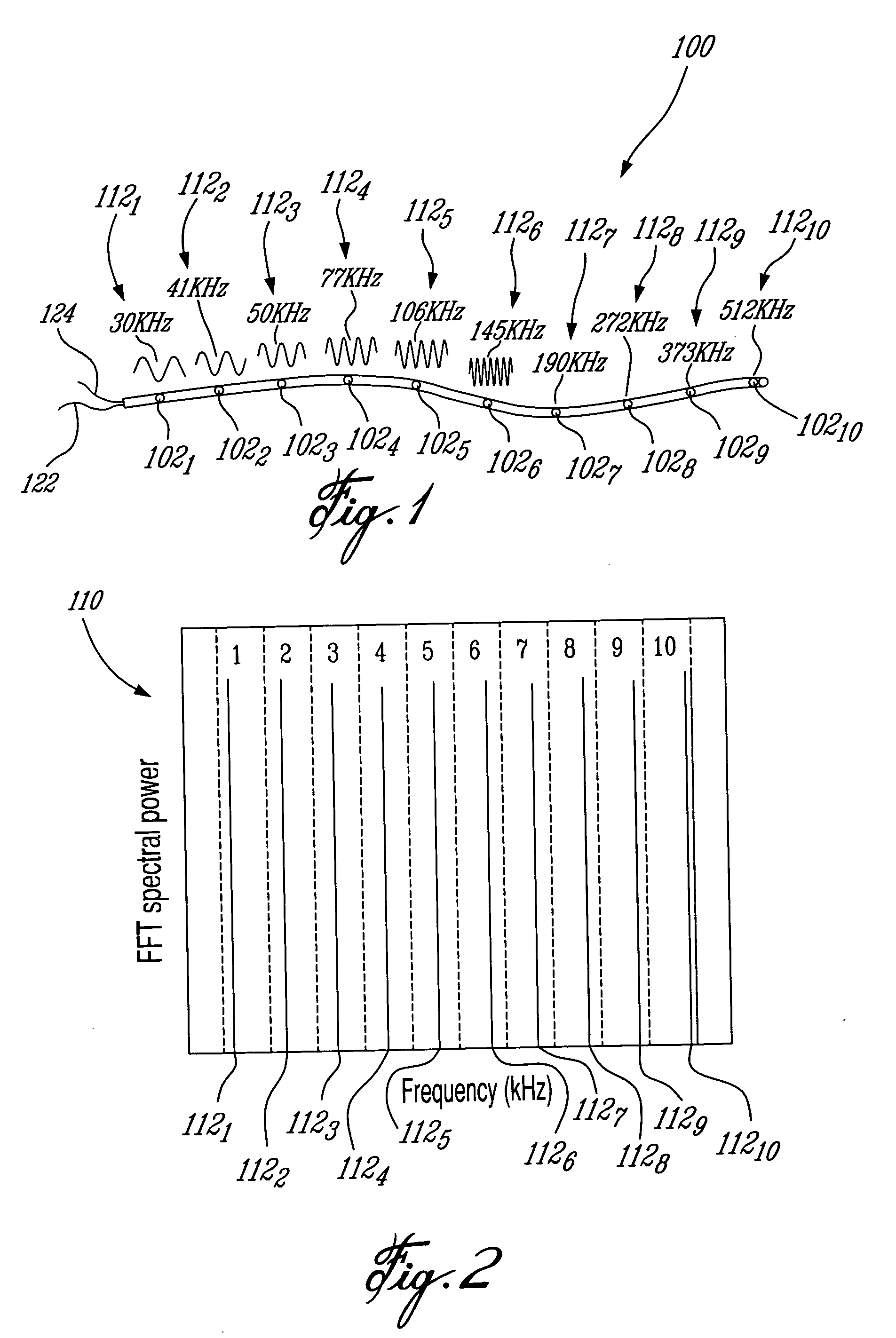
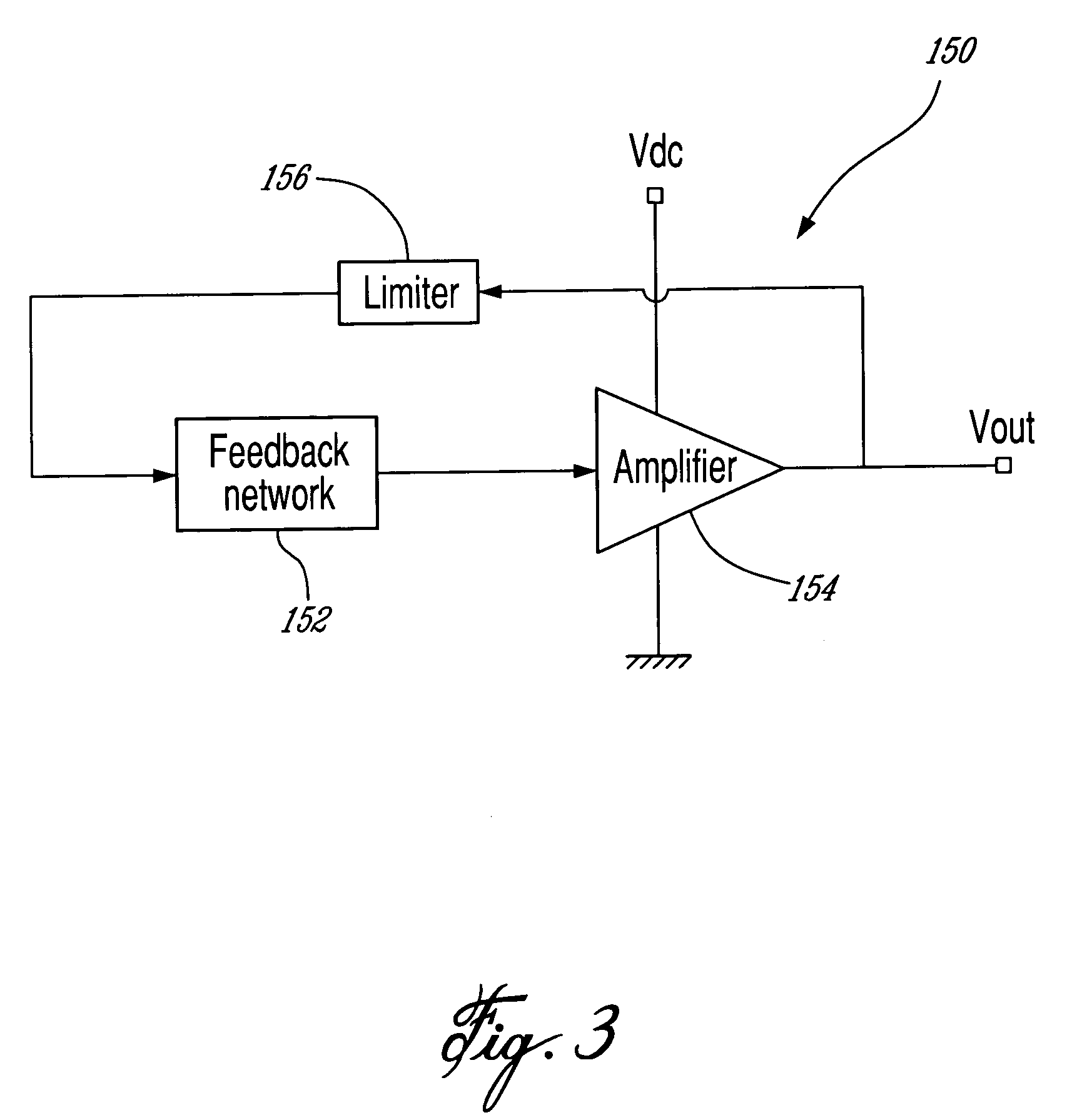
A sensor array for measuring various parameters in a machine environment, the sensor array comprising a number of oscillators, each of the oscillators comprising a feedback network, an amplifier and a limiter being connected together in a loop. The feedback network has a frequency which varies with the parameters to be measured. The amplifier consumes a current from a current supply and in cooperation with the feedback network produces a signal that alternates at the natural frequency of the feedback network. The limiter limits the amplitude of the signal within a predetermined amplitude range. All of the signals from the oscillators are multiplexed onto the output of the sensor array. Frequency analysis may then used to isolate the individual readings from each of the oscillators.

Description

CROSS-REFERENCE TO RELATED APPLICATION [0001] This application claims the benefits of U.S. provisional patent applications No. 60 / 583,596 filed Jun. 30, 2004; which is hereby incorporated by reference.FIELD OF THE INVENTION [0002] The present invention relates to an oscillator-based sensor array. BACKGROUND OF THE INVENTION [0003] In-flight monitoring of gas turbine engines allows the elaboration of adaptive maintenance plans. By periodically communicating engine data to its service center, the aircraft operator benefits from recommendations from maintenance experts. With additional sensors, maintenance tasks can focus on specific vulnerable parts, rather than reacting to the general behavior of the engine. Design engineers can also anticipate specific problems before they happen, and start working on pre-emptive design modifications. It is well recognized that development work spreads over the useful life of an engine, as some unexpected durability problems, often related to cyclic...

Claims


Application Information

Patent Timeline
Patent Type & Authority Applications(United States)
IPC IPC(8): G01M15/00G01B21/32G01M99/00G01D5/243G01F15/00G01K1/00G01L19/00G01M13/00
CPCF01D21/003F05D2260/80F05D2220/32G01D5/243
Inventor BROUILLETTE, MARTIN
Owner SCOPRA SCI & GENIE SEC
Learn More