
Adapter apparatus and network camera control method

Inactive Publication Date: 2006-03-23
PANASONIC CORP
View PDF0 Cites 32 Cited by
  • Summary
  • Abstract
  • Description
  • Claims
  • Application Information

AI Technical Summary

Benefits of technology

[0007] The present invention is provided to address the above-described problem. The main objective of the present invention is to provide an adapter apparatus and a network camera control method that allow users to use a network camera easily and inexpensively without depending on a personal computer.

Problems solved by technology

Such conventional technology, however, requires a personal computer for using a network camera.
This becomes an obstacle for those who are not familiar with personal computers, thereby discouraging them from using network cameras casually.
Furthermore, those who do not possess a personal computer need to prepare a personal computer in addition to a network camera, which puts an extra financial burden on those users.

Method used


Image

  • Adapter apparatus and network camera control method
  • Adapter apparatus and network camera control method
  • Adapter apparatus and network camera control method

Examples


Embodiment Construction

[0029] The embodiments of the present invention are explained in the following, in reference to the above-described drawings.

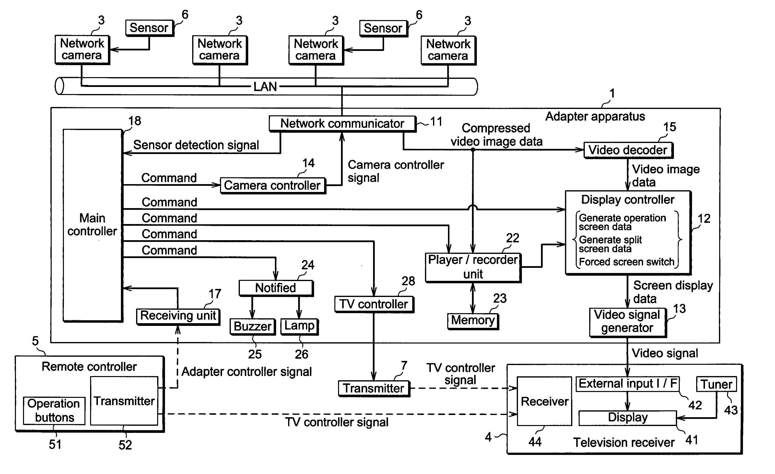
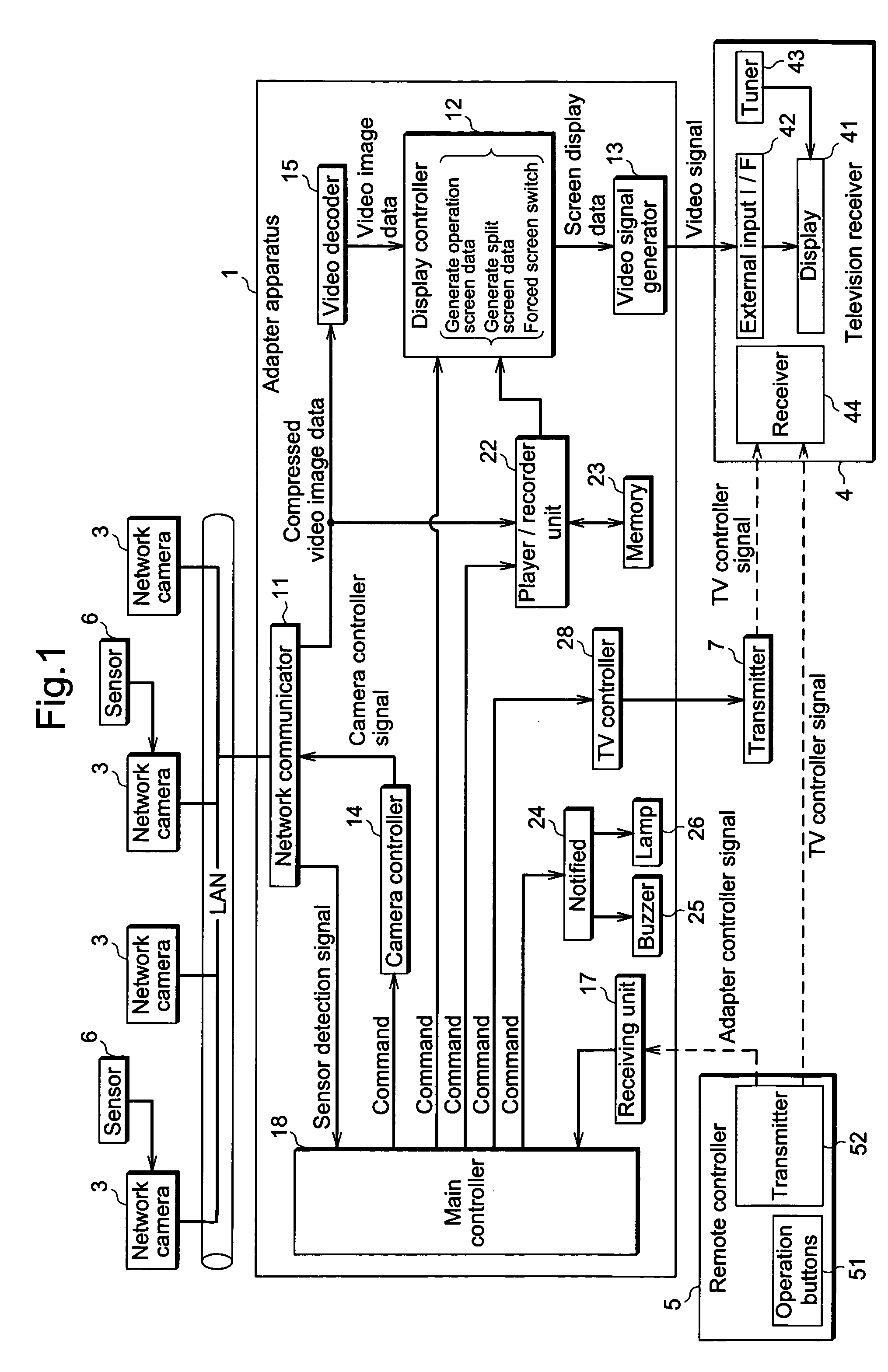
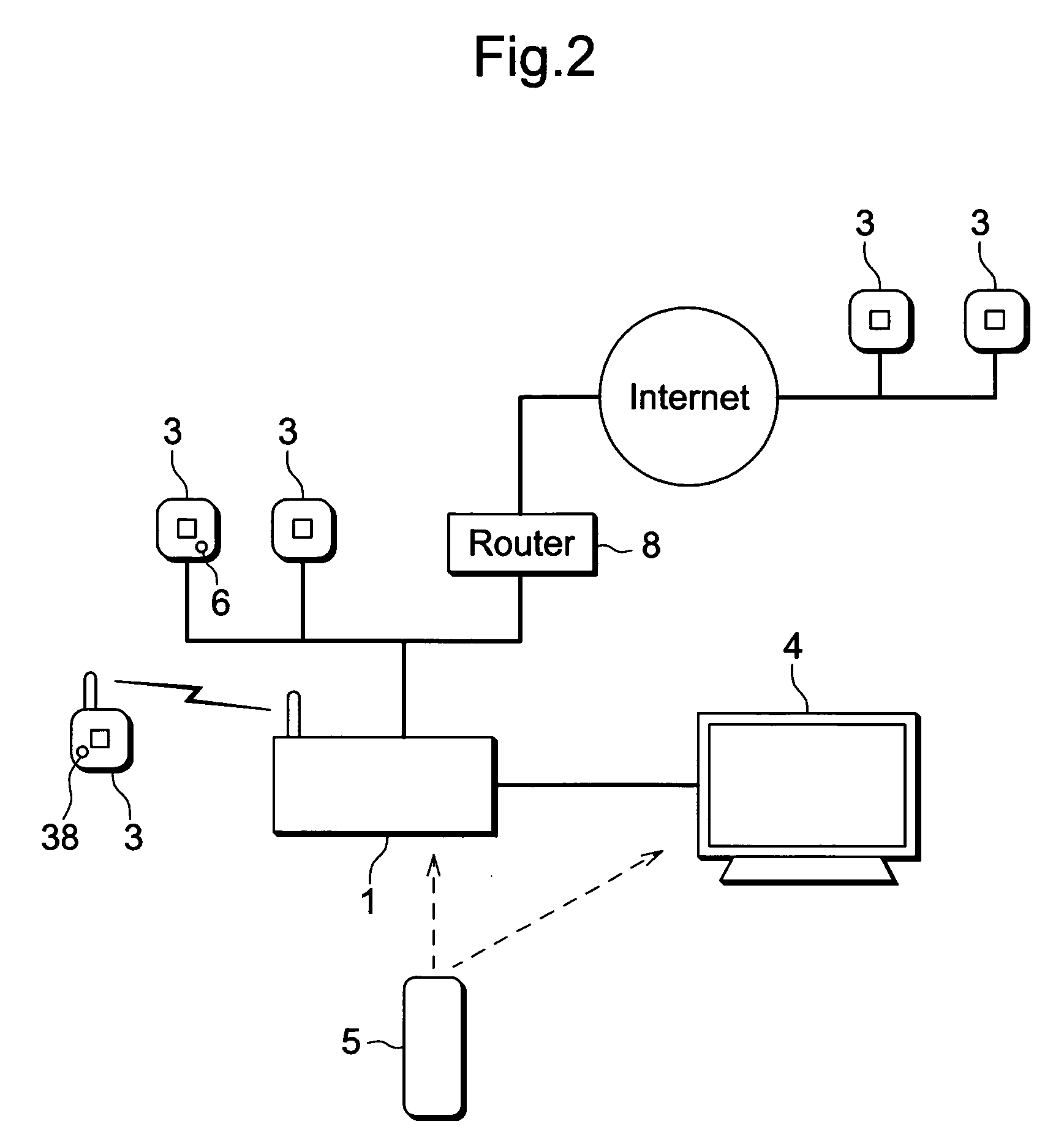
[0030]FIG. 1 is a functional block diagram illustrating an adapter apparatus according to the present invention. Adapter apparatus 1 is provided between network camera 3 and television receiver 4. Adapter apparatus 1 controls to display on television receiver 4 video images captured by network camera 3, and controls network camera 3. Adapter apparatus 1 includes network communicator 11, display controller 12 and video signal generator 13. Network communicator 11 performs communication with network camera 3 via the network (LAN). Display controller 12 generates screen display data based on video images captured by network camera 3 via network communicator 11. Video signal generator 13 converts screen display data generated by display controller 12 into video signals compatible with television receiver 4.

[0031] Video signal generator 13 outputs standard video ...


PUM


Abstract

The adapter apparatus according to the present invention is configured to include a network communicator, a display controller, a video signal generator, an input unit and a camera controller. The network communicator is used to perform communication with a network camera. The display controller generates screen display data, including video images data captured by the network camera via the network communicator. The video signal generator converts screen display data generated by the display controller into video signals compatible with a television receiver, and transmits the converted signals to the television receiver for display. The input unit is used by users to input instructions to the network camera. The camera controller generates predetermined camera control signals based on the instructions from the input unit, and transmits the generated signals to the network camera.

Description

BACKGROUND OF THE INVENTION [0001] 1. Field of the Invention [0002] The present invention relates to an adapter apparatus and a network camera control method that monitor and control a network camera. [0003] 2. Description of Related Art [0004] In recent years, so-called network cameras configured with a network interface have been a focus of attention. Such a network camera is connected to a personal computer as a network terminal, whereby video image data or control signals are sent / received between a network camera and a personal computer via the network. By using a personal computer, users are able to monitor video images captured by the network camera as easily as they browse web sites on the Internet, and have the network camera perform predetermined operations by remote control, including panning and tilting (Refer to Related Art 1, for example). [0005] [Related Art 1] Japanese Patent Laid-open Publication 2004-153373 [0006] Such conventional technology, however, requires a p...

Claims


Application Information

Patent Timeline
IPC IPC(8): H04N7/173H04N5/232H04N7/18H04N21/4223H04N21/637
CPCG08B13/19669G08B13/1968G08B13/19693H04N7/181H04N5/23203H04N5/23206G08B13/19695H04N23/66H04N23/661H04N23/632H04N23/695
Inventor HIROSAWA, KAZUTOYOMATSUMOTO, HIROSHIHANAOKA, HIDEYUKIYOSHIMATSU, KOUICHIKUROSE, TSUYOSHI
Owner PANASONIC CORP
Learn More