Combustion chamber for a gas turbine with at least two resonator devices
- Summary
- Abstract
- Description
- Claims
- Application Information
AI Technical Summary
Benefits of technology
Problems solved by technology
Method used
Image
Examples
Embodiment Construction
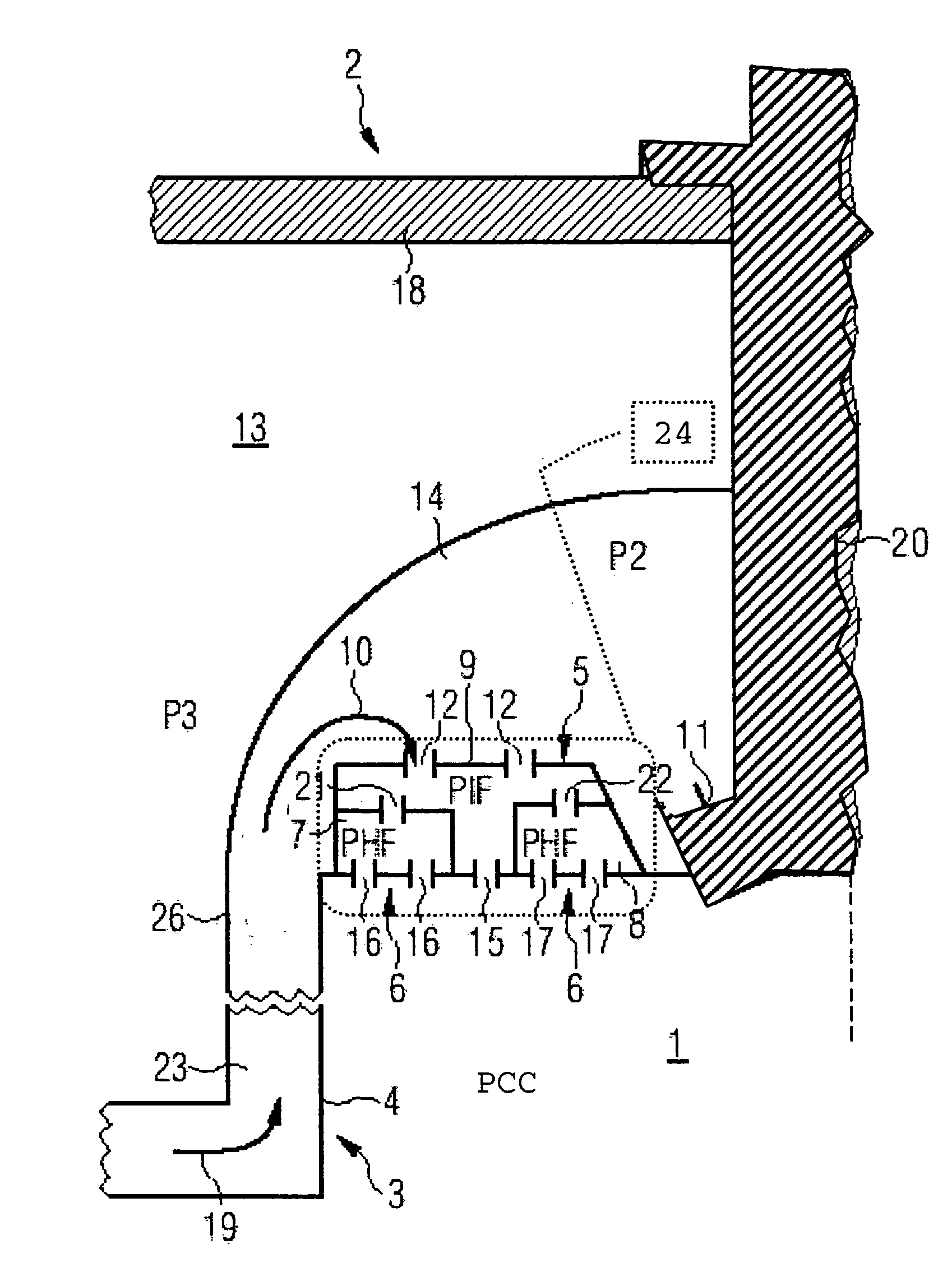
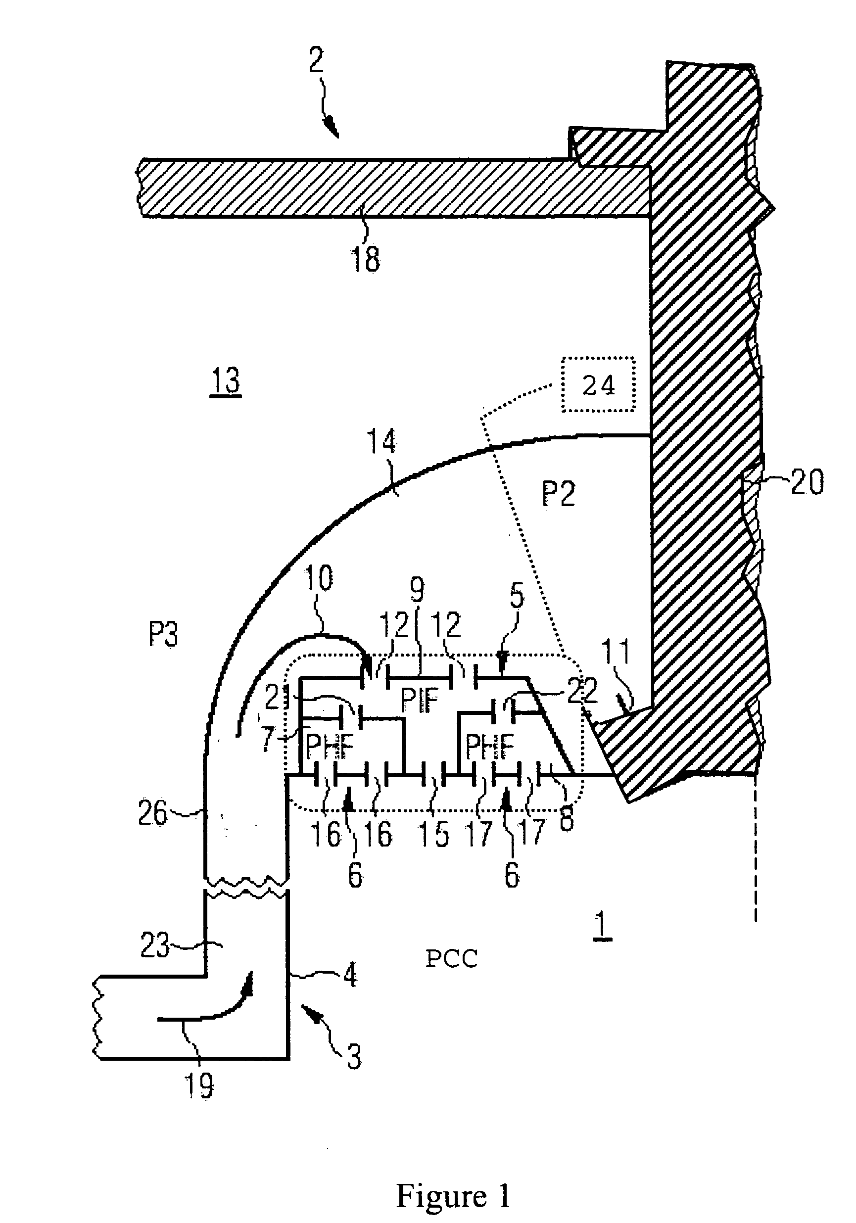
[0021]FIG. 1 diagrammatically shows a portion from the head plate 24 of a combustion chamber 1 of a gas turbine 2, as an embodiment by way of example of a combustion chamber according to the invention. The gas turbine 2 includes an outer casing 18 which surrounds the combustion chamber 1. Provided at the combustion chamber 1 is a burner 20 of which only a portion is illustrated in the Figure and at the sides of which are arranged air inlet valves 25 for the feed of air for the combustion process (only one of the air inlet valves 25 can be seen in FIG. 1). The air is passed through the chamber wall 3 to the air inlet valves 25. The chamber wall 3 includes a rear chamber wall 26 and a lining 4 which forms a front chamber wall. The intermediate space 23 between the rear chamber wall 26 and the lining 4 in that arrangement forms at least one flow passage for the feed of air to the air inlet valves 25. The air flowing through the flow passage is not intended exclusively for the combustio...
PUM
 Abstract
Description
Claims
Application Information
 - R&D
- Intellectual Property
- Life Sciences
- Materials
- Tech Scout
- Unparalleled Data Quality
- Higher Quality Content
- 60% Fewer Hallucinations
Browse by: Latest US Patents, China's latest patents, Technical Efficacy Thesaurus, Application Domain, Technology Topic, Popular Technical Reports.
© 2025 PatSnap. All rights reserved.Legal|Privacy policy|Modern Slavery Act Transparency Statement|Sitemap|About US| Contact US: help@patsnap.com


