
Monitoring the flow of messages received at a server

a server and message technology, applied in the field of processing electronic messages, can solve the problems of significant harm to electronic files and systems of companies, and administrators cannot distinguish,

Inactive Publication Date: 2006-03-16
IRONPORT SYST
View PDF99 Cites 397 Cited by
  • Summary
  • Abstract
  • Description
  • Claims
  • Application Information

AI Technical Summary

Benefits of technology

"The present invention provides a system for monitoring the flow of email messages received by a server. The invention allows administrators to easily and efficiently monitor the flow of email messages and take steps to deal with spam and virus infected email messages. The invention distinguishes between desirable and undesirable email messages and allows administrators to identify patterns and take appropriate actions based on the information. The invention also provides a graphical user interface for monitoring email messages. Overall, the invention improves the efficiency and effectiveness of monitoring email messages and helps to protect against spam and virus outbreaks."

Problems solved by technology

However, traditional mail flow monitoring approaches only allow the administrators to see the overall total flow of email messages into the MTA, and these approaches do not allow the administrators to distinguish between email messages that the administrators want to let into the system served by the MTA (e.g., legitimate email messages from the company's partners and customers) from email messages that the administrators want to avoid, such as spam that often comprises the majority of messages being sent to the MTA or virus infected email messages that can cause significant harm to a company's electronic files and systems.

Method used


Image

  • Monitoring the flow of messages received at a server
  • Monitoring the flow of messages received at a server
  • Monitoring the flow of messages received at a server

Examples


Embodiment Construction

[0016] A method and apparatus for monitoring email messages receive by a server is described. In the following description, for the purposes of explanation, numerous specific details are set forth in order to provide a thorough understanding of the present invention. It will be apparent, however, to one skilled in the art that the present invention may be practiced without these specific details. In other instances, well-known structures and devices are depicted in block diagram form in order to avoid unnecessarily obscuring the present invention.

[0017] In the following description, the various functions shall be discussed under topic headings that appear in the following order:

[0018] I. Structural and Functional Overview [0019] A. Introduction [0020] B. Structural Overview of Monitoring Email Messages [0021] C. Functional Overview of Monitoring Email Messages

[0022] II. Collecting and Aggregating Message Information [0023] A. Using a Queue to Store Message Information [0024] B. T...


PUM


Abstract

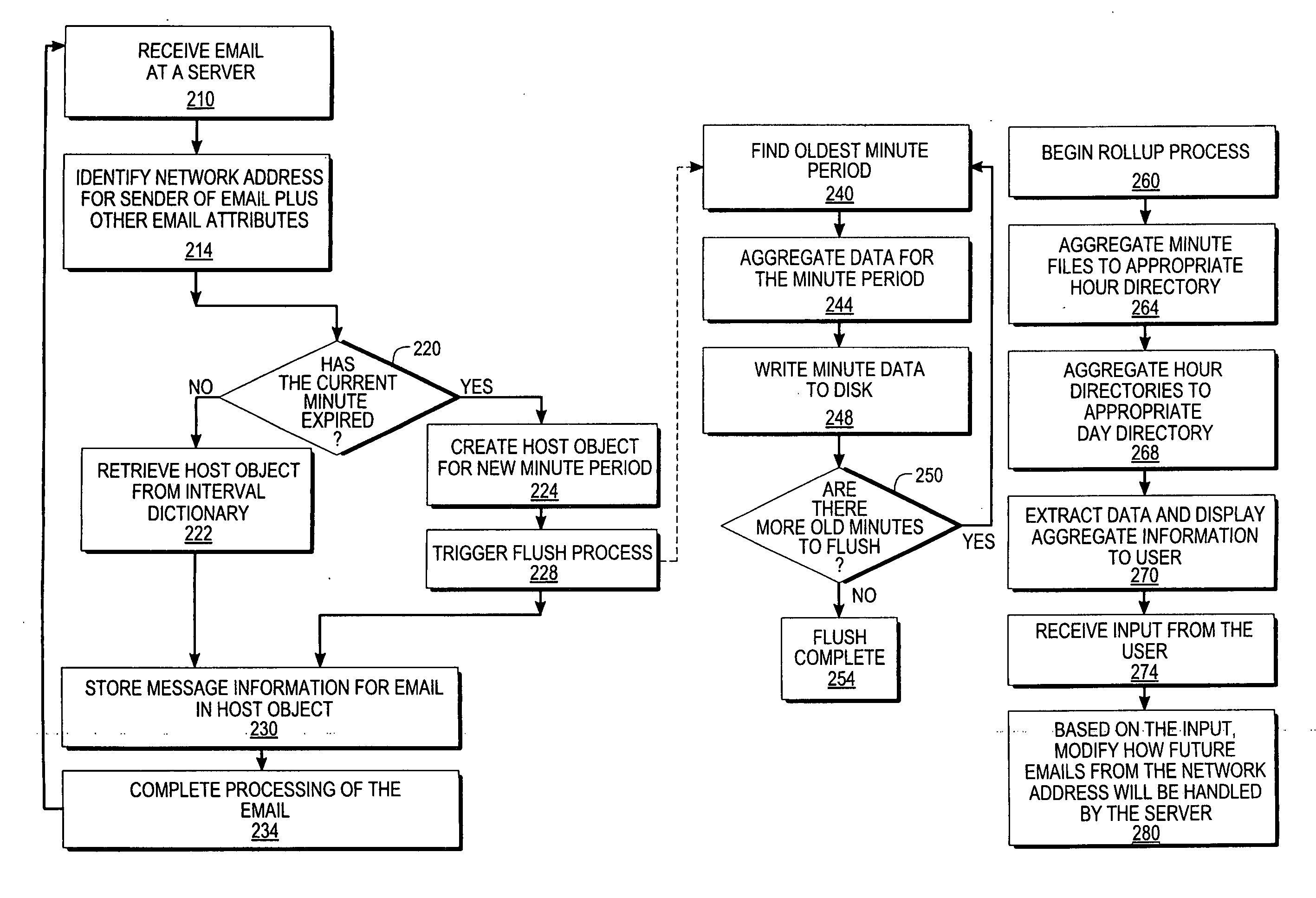
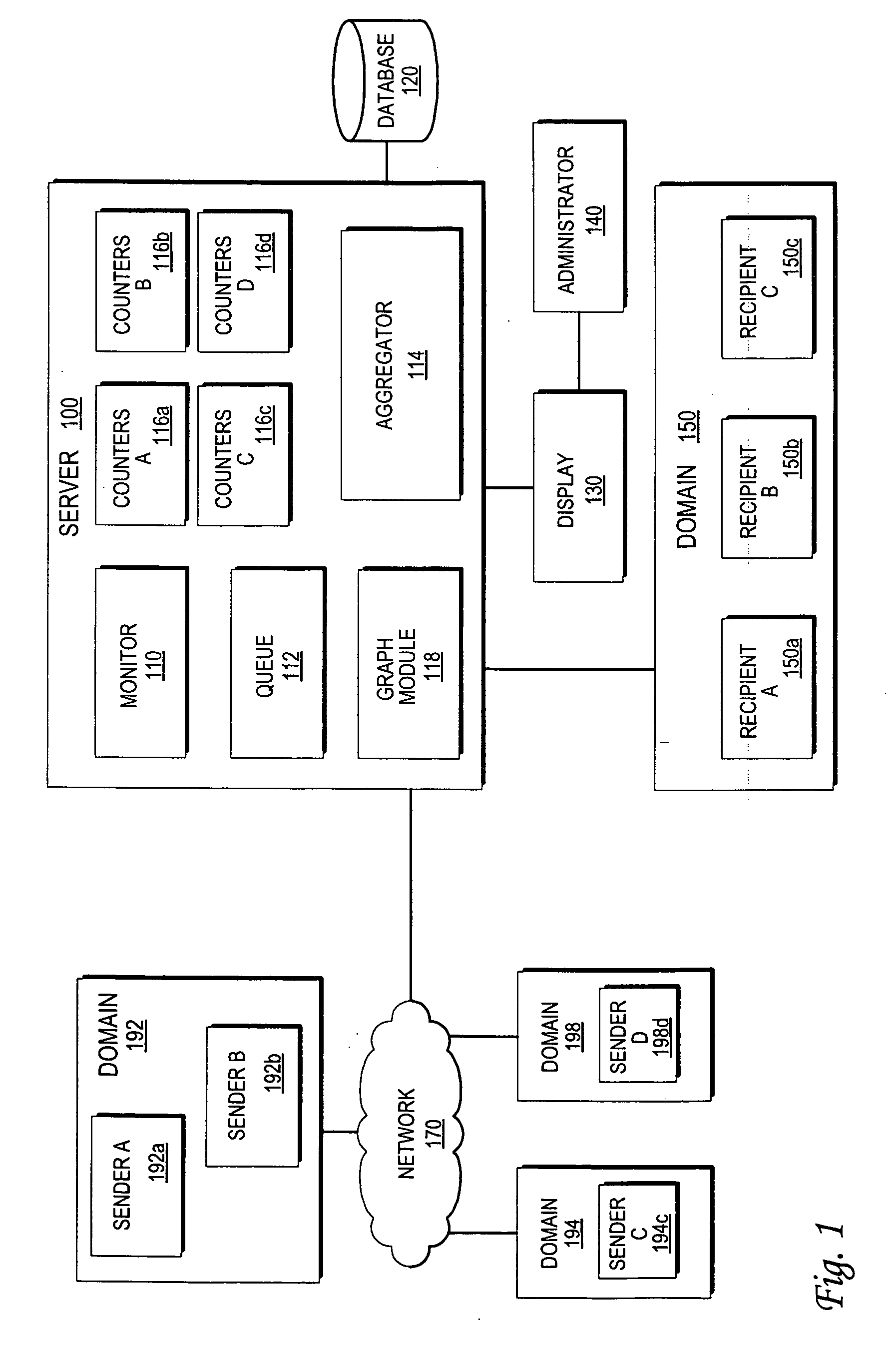
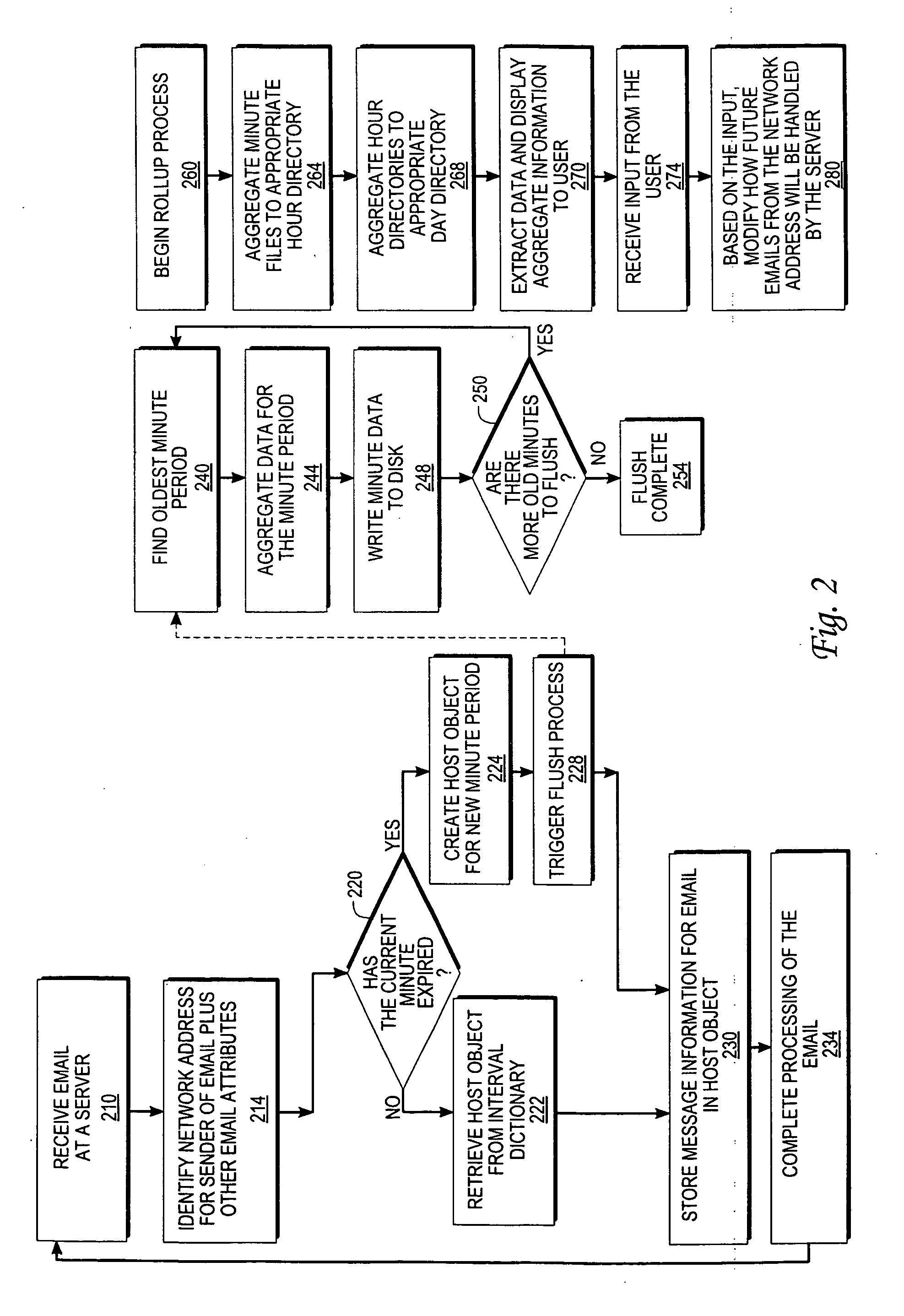
An approach for monitoring electronic messages received at a server is disclosed. Message information for a plurality of electronic messages received at the server: is determined and stored in a queue. Based on the queue, aggregate information is generated for a particular network address of a plurality of network addresses. The aggregate information is generated for each time interval of a plurality of time intervals and displayed for the plurality of time intervals. In some implementations, input from a user is received, and based on the input, a modification is made regarding how future electronic messages from the particular network address are handled by the server. In some implementations, combined aggregate information is generated for two or more network addresses and then displayed. In some implementations, aggregate policy information indicating which policies have been applied to the electronic messages is generated and displayed for the time intervals.

Description

PRIORITY CLAIM AND RELATED APPLICATIONS [0001] This application claims domestic priority under 35 U.S.C. §119(e) from prior U.S. provisional application Ser. No. 60 / 575,658, entitled “PROVIDING TEMPORARY ACCESS TO A NETWORK DEVICE, USING DESTINATION DOMAIN-BASED BOUNCE PROFILES, MONITORING THE FLOW OF MESSAGES FROM SENDERS, AND CONTROLLING THE FLOW OF MESSGES FROM SENDERS,” filed May 29, 2004, naming Paul J. Clegg, Charlie S. Slater, R. Brian Harrison, Lonhyn Jasinskyj, Ben Cottrell, Eric Huss, Craig Sprosts, Krishna Srinivasan, Peter Schlampp, Shun Chen, Robert Brahms, Daniel Quinlan, and Brennan H. Evans as inventors, the entire disclosure of which is hereby incorporated by reference for all purposes as if fully set forth herein. [0002] This application is related to: (1) co-pending non-provisional application Ser. No. 10 / ______ (Attorney Docket No 60063-0055), filed concurrently with the present application, entitled “MANAGING CONNECTIONS AND MESSAGES AT A SERVER BY ASSOCIATING D...

Claims


Application Information

Patent Timeline
Patent Type & Authority Applications(United States)
IPC IPC(8): G06F15/16G06F15/173G06Q10/00H04L12/58
CPCG06Q10/107H04L51/12H04L12/5855H04L12/585H04L51/214H04L51/212
Inventor SLATER, CHARLES S.CLEGG, PAUL J.EVANS, BRENNAN H.SCHLAMPP, PETER
Owner IRONPORT SYST
Learn More