
Method of testing components designed to perform real-time, high resource functions

a technology of components and functions, applied in the direction of program control, specific program execution arrangements, program initiation/switching, etc., can solve the problems of inability to meet the requirements of radio frequency frequency synchronization, and inability to meet the requirements of radio frequency synchronization

Inactive Publication Date: 2006-03-16
RADIOSCAPE
View PDF3 Cites 40 Cited by
  • Summary
  • Abstract
  • Description
  • Claims
  • Application Information

AI Technical Summary

Benefits of technology

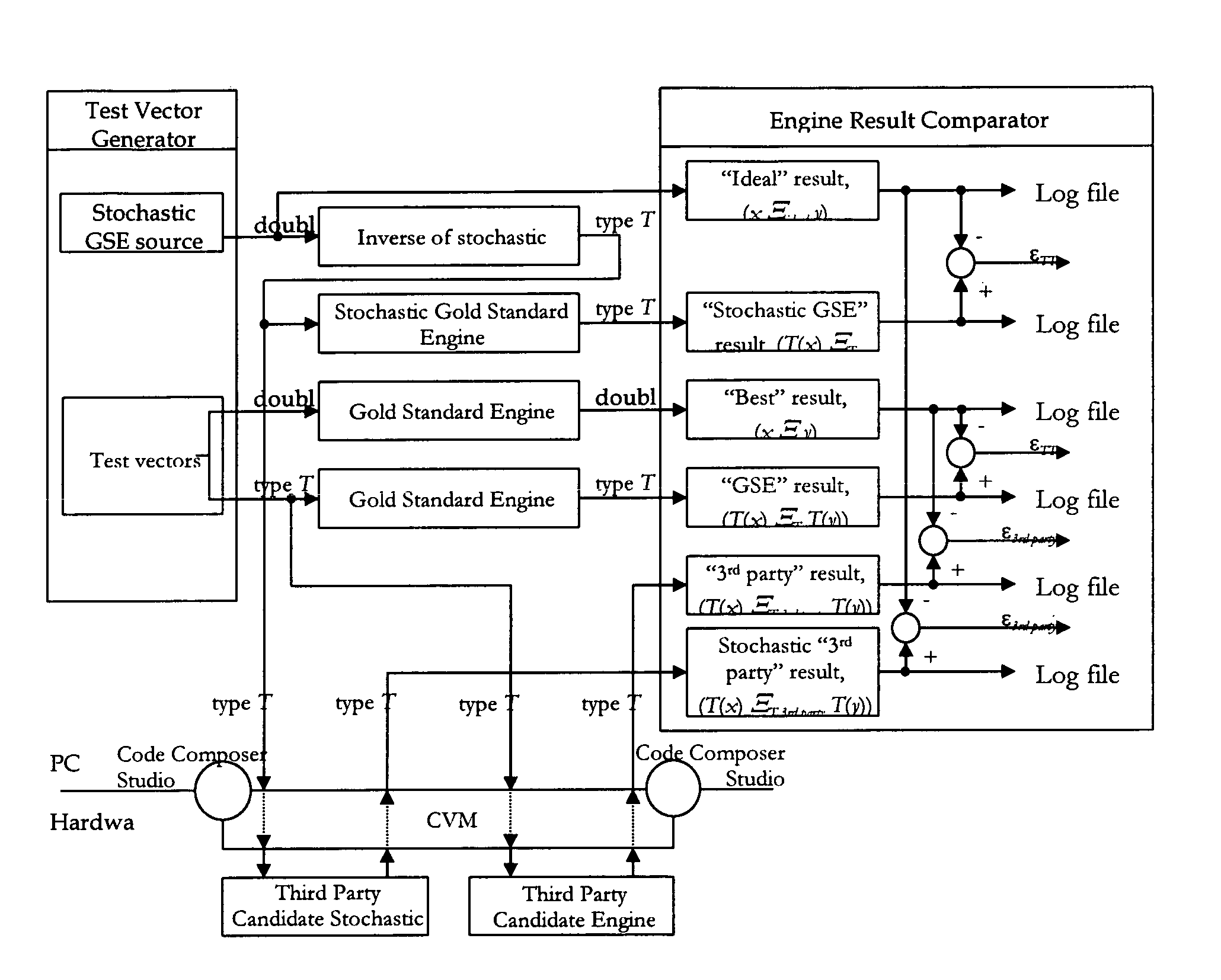
[0024] By allowing for engines to be conformance tested against an accurate behavioural description of the high resource function (i.e. the reference engine), it is possible to validate and guarantee the behavioural equivalence of that engine to any other engine that passes the same conformance test: this gives the system designer the ability to choose from one of several different target platform / engine pairs when actually deploying a system, because he knows that whichever platform he chooses, he will have an engine that runs on that platform to perform the high resource function in a way that is behaviourally the same as any other engine (specific to a different platform) he might have chosen. An engine should be expansively construed to cover any kind of component that implements a high resource function.

Problems solved by technology

Modern communications system developers are encountering a number of challenges: The new radio standards, such as UMTS, are more complex than any previous standards.
In a typical design flow the tools do not work together well, which means that engineers are forced to make hardware choices early on in the product development cycle.
The existing design flows are flawed, since tools in the design flow do not work together well and are hard to use.
Hardware and software systems are becoming increasingly complex, requiring the use of large development teams, often in different geographical locations.
This bursty processing challenges the traditional scheduling approaches of embedded engineering.

Method used


Image

  • Method of testing components designed to perform real-time, high resource functions
  • Method of testing components designed to perform real-time, high resource functions
  • Method of testing components designed to perform real-time, high resource functions

Examples


Embodiment Construction

1. Overview of the Communication Virtual Machine (CVM)

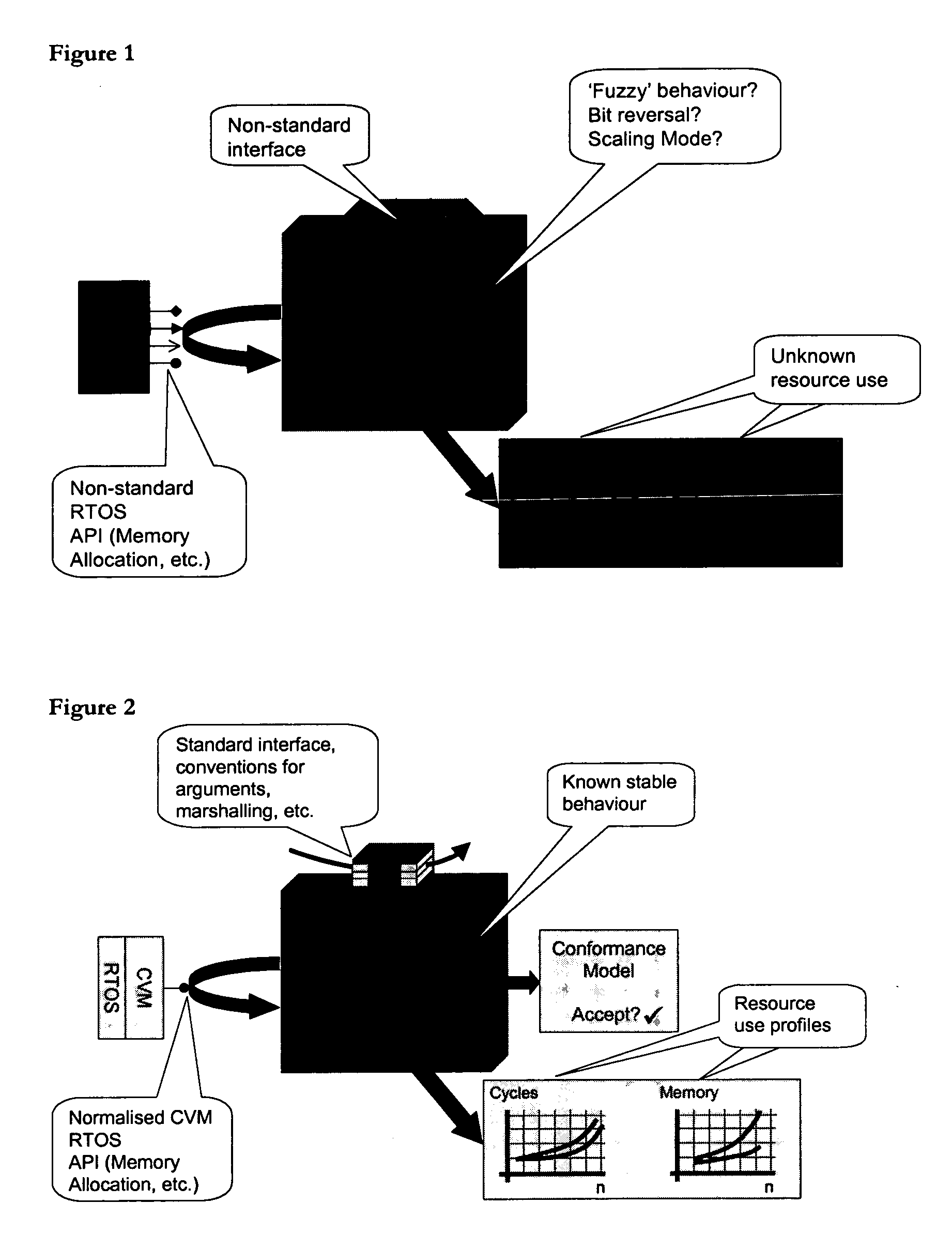
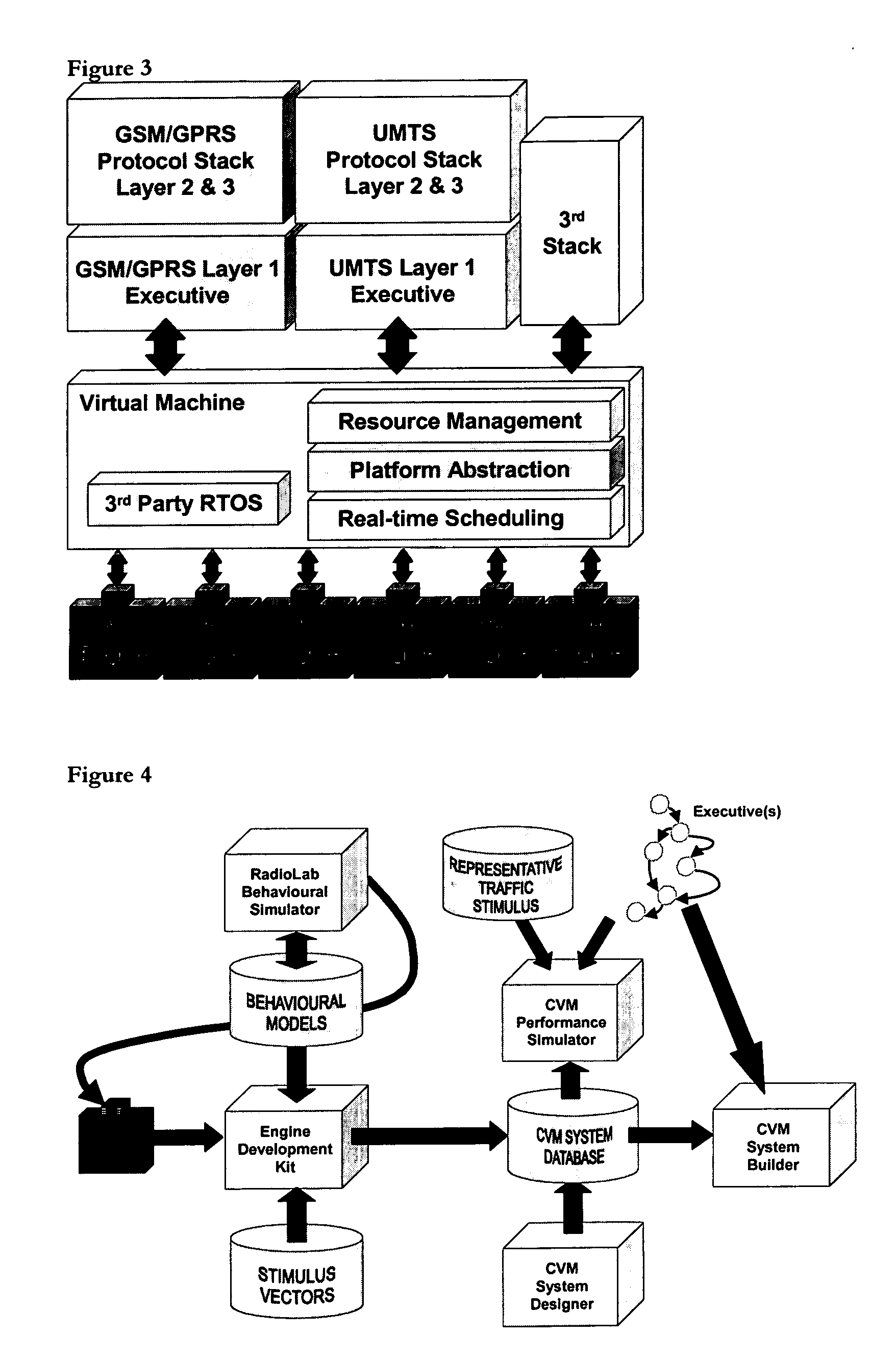
[0046] The CVM is a combination of run-time middleware and design-time tools that together help users implement a development paradigm for complex communication stacks.

[0047] The underlying conceptual model for CVM is as follows. We assume that a communication stack (particularly at layer 1) may be decomposed into: [0048] High-resource, largely-application-neutral components, which will probably be implemented either in dedicated hardware or in highly platform-optimised software. These we call engines, and examples would be: FFT, FIR filter, vector multiply, etc. In the general case (where the particular CVM engine constraints are not met), we refer to such blocks as high-resource functions, or HRFs. [0049] Low-resource, largely application-specific components, which will probably contain nothing that inherently binds them to a particular underlying hardware substrate. These we call executives, and examples would be the overal...


PUM


Abstract

A method of testing an engine designed to perform a real-time DSP or communications high resource function on an embedded target platform, the method comprising the steps of: (a) developing a reference engine for the high resource function, the reference engine performing the same functionality as the engine but running on a desktop computer and not the target platform; (b) conformance testing the engine against the reference engine by measuring the functionality of the engine when stimulated by stimulus vectors and comparing that functionality against the reference engine.

Description

BACKGROUND OF THE INVENTION [0001] 1. Field of the Invention [0002] This invention relates to a method of testing components designed to perform real-time, high resource functions. [0003] 2. Description of the Prior Art [0004] Modern communications system developers are encountering a number of challenges: [0005] The new radio standards, such as UMTS, are more complex than any previous standards. [0006] Handset developers now have to cope with multiple standards, such as GSM and UMTS, on the same DSP. Consequently there is an increasing need for multi-system integration, where communications stacks from more than one standard have to live side by side on the same platform. [0007] In a typical design flow the tools do not work together well, which means that engineers are forced to make hardware choices early on in the product development cycle. [0008] The existing design flows are flawed, since tools in the design flow do not work together well and are hard to use. [0009] Hardware a...

Claims


Application Information

Patent Timeline
IPC IPC(8): G06F19/00G06F9/455G06F9/48G06F17/50
CPCG06F9/45537G06F17/5045G06F17/5022G06F9/4887G06F30/30G06F30/33G06F30/3308
Inventor FERRIS, GAVIN ROBERT
Owner RADIOSCAPE
Learn More