Burner assembly
- Summary
- Abstract
- Description
- Claims
- Application Information
AI Technical Summary
Benefits of technology
Problems solved by technology
Method used
Image
Examples
Embodiment Construction
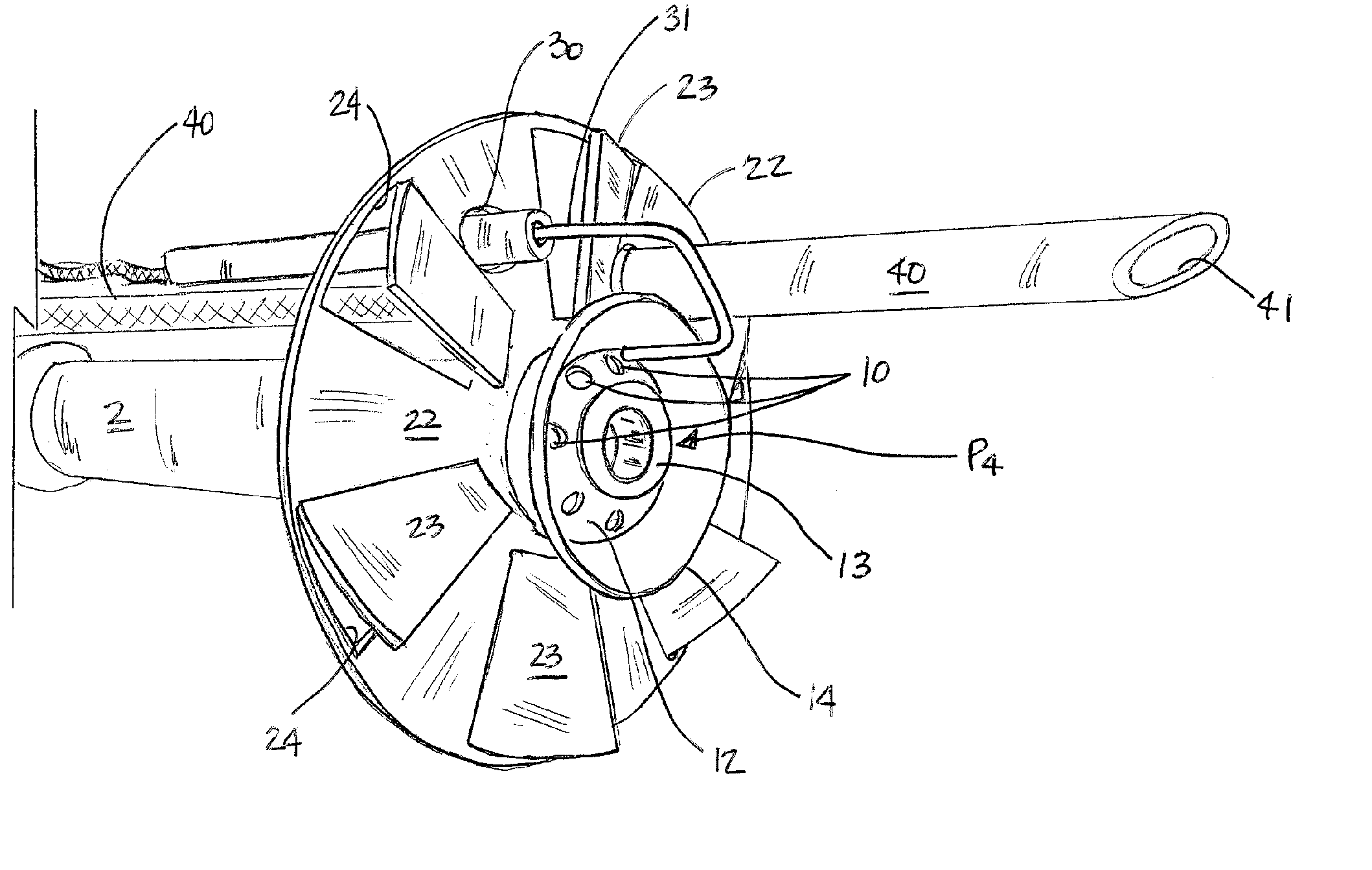
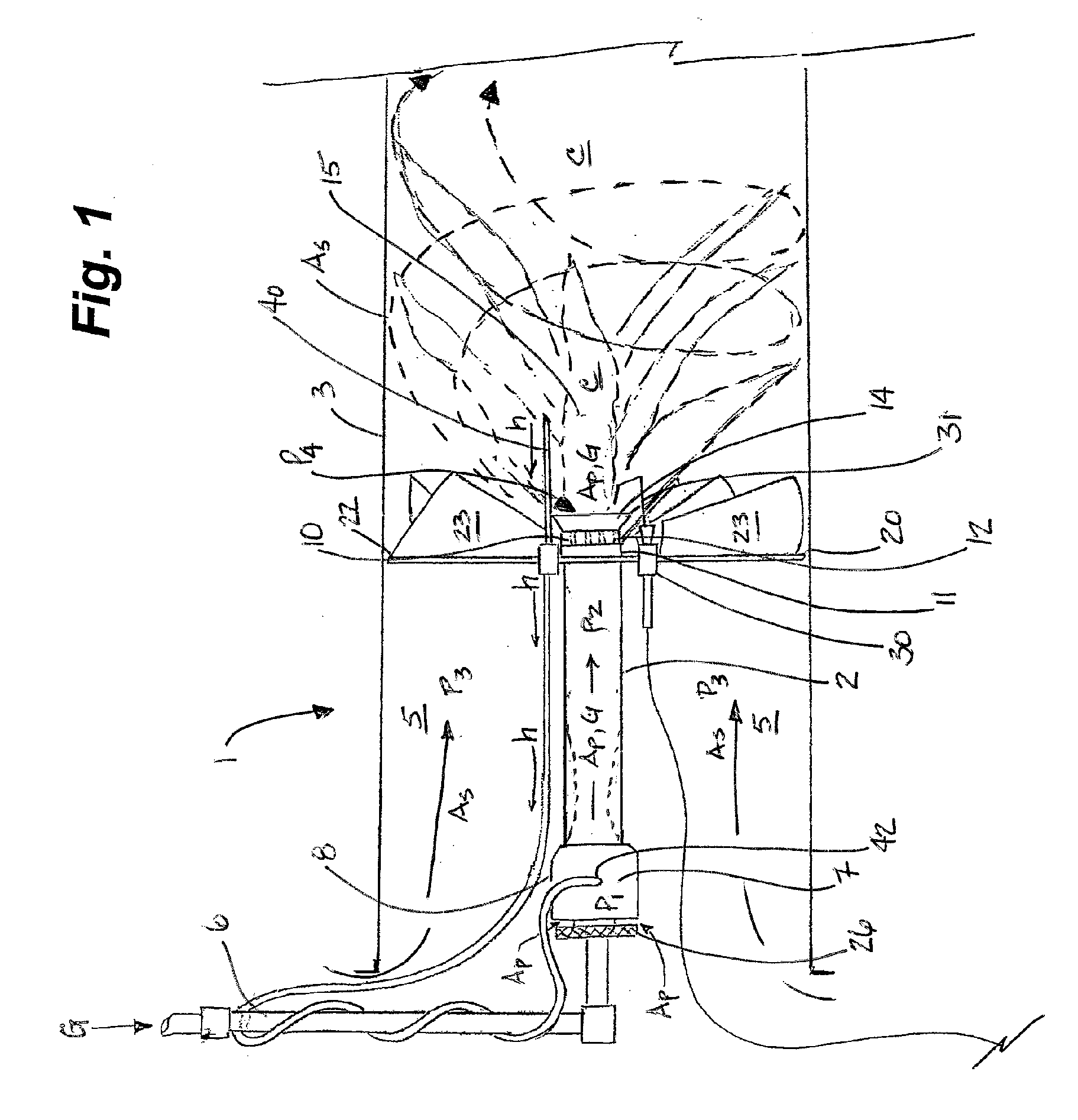
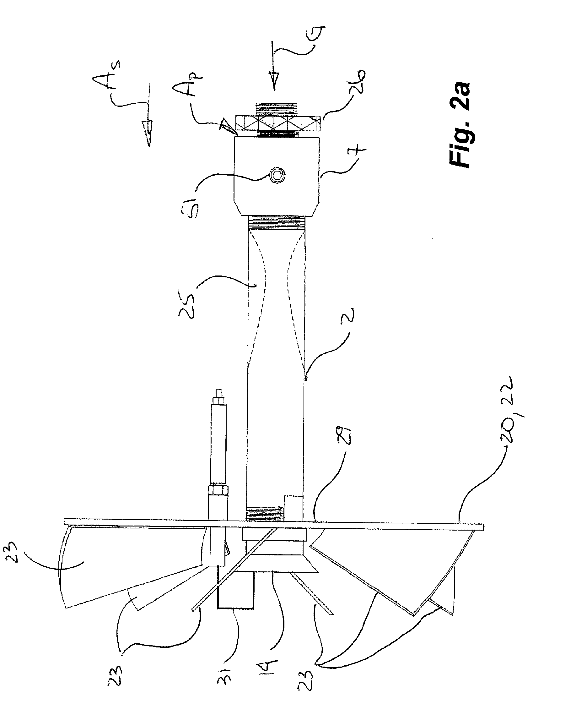
[0019] Having reference to FIGS. 1-8, a burner assembly 1 according to an embodiment of the invention is shown.
[0020] As shown in FIG. 1, the burner assembly 1 comprises a tubular barrel 2 which is mounted in the bore of a firetube or other such housing 3, forming an annulus 5 therebetween. The tubular barrel 2 conducts primary fuel gas G from a gas inlet 6 at a base or proximal end 8 of the tubular barrel 2 to a burner head 12 at a distal end 11 of the tubular barrel 2. The barrel 2 is typically of conventional configuration. The gas at the gas inlet 6 is fed at a first pressure P1 through an orifice 50 to a mixer head 7 (FIGS. 5, 7 and 8) at the proximal end 8. Primary combustion air Ap is drawn into the mixer head 7 via natural draft and the combined air Ap and gas G are mixed therein and flow through the tubular barrel 2 at a second pressure P2 to an orifice or plurality of orifices 10 in the burner head 12. The air and gas discharge from the burner head 12 at a nozzle tip 13 a...
PUM
 Abstract
Description
Claims
Application Information
 - R&D
- Intellectual Property
- Life Sciences
- Materials
- Tech Scout
- Unparalleled Data Quality
- Higher Quality Content
- 60% Fewer Hallucinations
Browse by: Latest US Patents, China's latest patents, Technical Efficacy Thesaurus, Application Domain, Technology Topic, Popular Technical Reports.
© 2025 PatSnap. All rights reserved.Legal|Privacy policy|Modern Slavery Act Transparency Statement|Sitemap|About US| Contact US: help@patsnap.com


