
Coolant pumping device

a pumping device and cooling technology, applied in the direction of pumping, positive displacement liquid engine, machine/engine, etc., can solve the problems of high noise, difficult starting of the rotor in such a condition, and difficult starting of the rotor under such a condition, so as to enhance the operation smoothness improve heat removal efficiency, and enhance the effect of the smooth operation of the pumping devi

Inactive Publication Date: 2006-03-16
CHEN TSUNG CHIN
View PDF9 Cites 12 Cited by
  • Summary
  • Abstract
  • Description
  • Claims
  • Application Information

AI Technical Summary

Benefits of technology

[0007] An object of the present invention is to provide a coolant pumping device that effectively overcomes the problem of starting occurring in the conventional designs and enhances the operation smoothness of the pumping device thereby improving heat removal efficiency.
[0008] Another object of the present invention is to provide a coolant pumping device comprising a sensing element for detecting the polarity of a rotor magnet in order to enhance the operation smoothness of the pumping device.
[0009] To achieve the above objects, in accordance with the present invention, there is provided a coolant pumping device, particularly suitable for liquid based cooling operation of computer devices, comprising a casing containing a stator portion of an electrical motor, comprising windings and silicon steel plates, and a control circuit board. A first chamber is formed atop the casing in which a blade assembly is rotatably received for effecting circulation of a coolant. A second chamber delimited by a cylindrical wall fixed inside the casing rotatably receives a rotor magnet, which is driven by the stator portion. The blade assembly / is fixed to the rotor magnet. Slots are defined in the casing for retaining the control circuit board. A Hall IC, serving as a sensing element for detecting polarity of the magnet inside the second chamber is electrically connected to the circuit board and is fixed inside the casing. The sensing element provides a detection signal to the control circuit board to enhance operation smoothness of the pumping device.

Problems solved by technology

The conventional coolant pumping device suffers a drawback that when the magnetic poles of the magnet are exactly opposite to the magnetic poles of the magnetic field induced by the windings, the rotor magnet becomes stationary and starting rotation of the rotor in such a condition is difficult for the magnet is attracted by the magnetic field of the windings and no repulsive force is induced between the magnet and the windings.
Starting the rotation of the rotor under such a condition is difficult, and high level of noise can be generated.
As a result, over-heating of the computer device may occur and failure of the operation of the computer device results.

Method used


Image

  • Coolant pumping device
  • Coolant pumping device
  • Coolant pumping device

Examples


Embodiment Construction

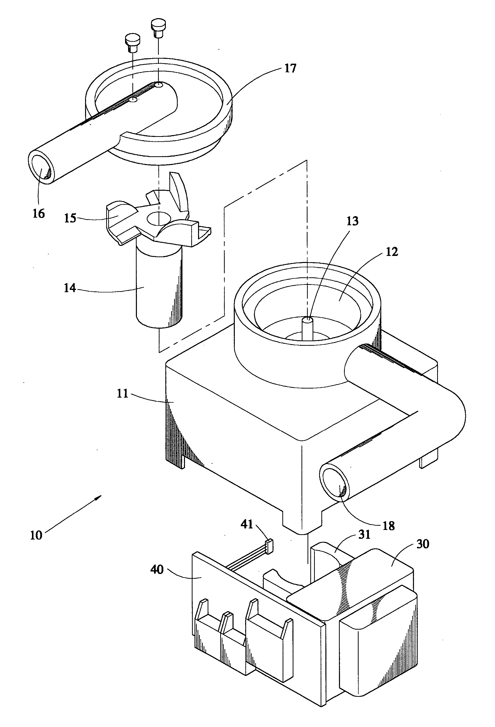
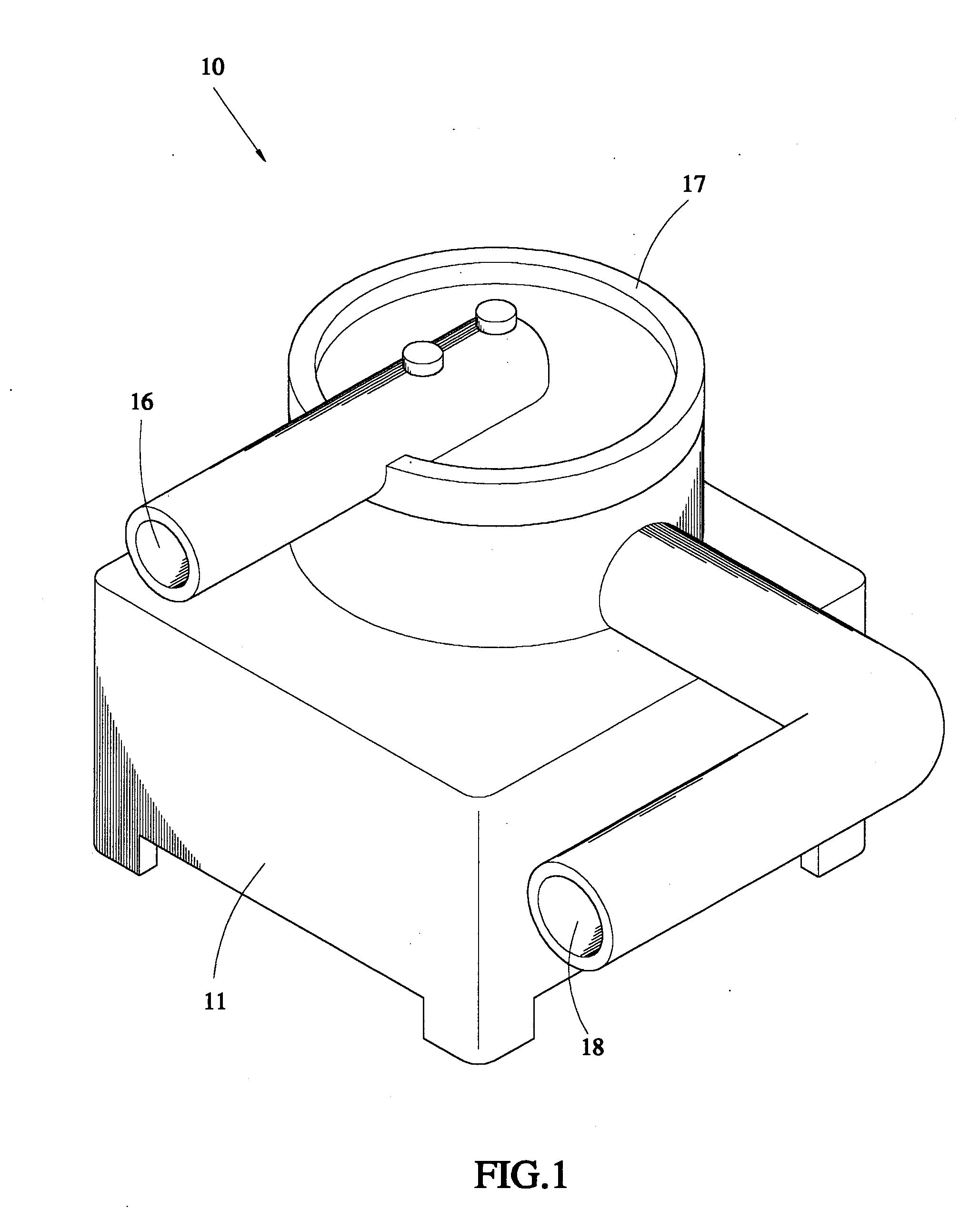
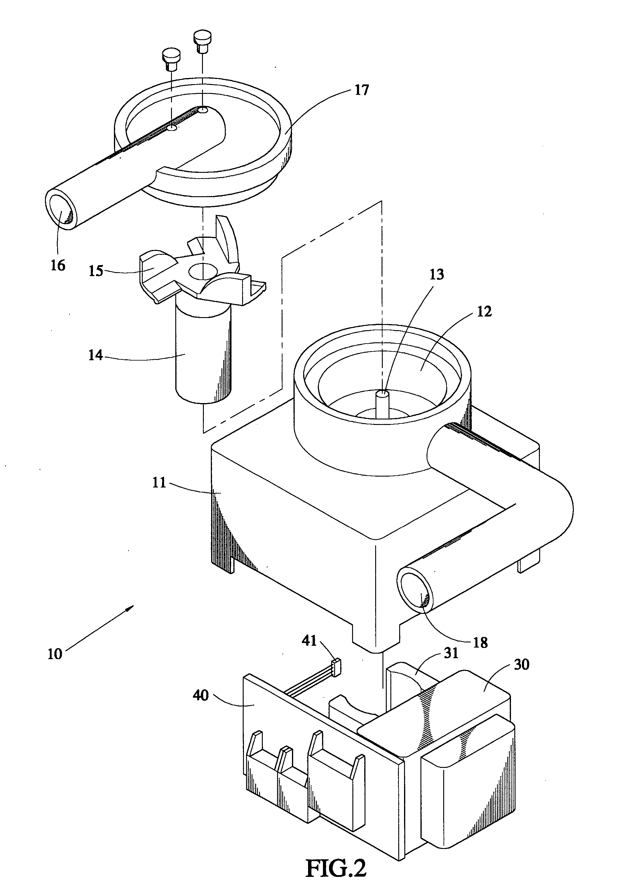
[0016] With reference to the drawings and in particular to FIGS. 1 and 2, which show, respectively, a perspective view and an exploded view of a coolant pumping device constructed in accordance with the present invention, generally designated with reference numeral 10, the coolant pumping device 10 comprises a casing 11 defining an interior space (not labeled) in which parts constituting a stator portion of an electrical motor are arranged, including at least windings 30 and silicon steel plates 31. A circuit board 40 on which a circuit for controlling power supplied to the stator portion is formed is also arranged inside the casing 10 and in electrical connection with the stator portion.

[0017] A first chamber 12 is formed atop the casing 11. In the embodiment illustrated, the first chamber 12 comprises a cylindrical outer wall from which a coolant outlet 18, which in the embodiment illustrated is in the form of a shaped tube in fluid communication with the first chamber 12, extend...


PUM


Abstract

A coolant pumping device includes a casing containing a stator portion of an electrical motor, including windings and silicon steel plates, and a control circuit board. A first chamber is formed atop the casing in which a blade assembly is rotatably received for effecting circulation of a coolant. A second chamber delimited by a cylindrical wall fixed inside the casing rotatably receives a rotor magnet, which is driven by the stator portion. The blade assembly is fixed to the rotor magnet. Slots are defined in the casing for retaining the control circuit board. A Hall IC, serving as a sensing element for detecting polarity of the magnet inside the second chamber is electrically connected to the circuit board and is fixed inside the casing. The sensing element provides a detection signal to the control circuit board to enhance operation smoothness of the pumping device.

Description

BACKGROUND OF THE INVENTION [0001] 1. Field of the Invention [0002] The present invention generally relates to a coolant pumping device for circulating coolant through a computer device, and in particular to a coolant pumping device comprising a sensing element for detecting polarity of a rotor magnet to enhance operation smoothness of the pumping device. [0003] 2. The Related Art [0004] A conventional coolant pumping device of the above-mentioned type comprises a rotor magnet rotatably fit over an axle, which is driven by a stator portion comprising windings and silicon steel plates. The rotor magnet in turn drives the rotation of a blade assembly to effect circulation of coolant. [0005] The conventional coolant pumping device suffers a drawback that when the magnetic poles of the magnet are exactly opposite to the magnetic poles of the magnetic field induced by the windings, the rotor magnet becomes stationary and starting rotation of the rotor in such a condition is difficult for...

Claims


Application Information

Patent Timeline
Patent Type & Authority Applications(United States)
IPC IPC(8): F04B17/00F04B35/04F04B17/04F04D13/06
CPCH02K5/128F04D13/064H02K11/0021H02K11/215
Inventor CHEN, TS'UNG CHIN
Owner CHEN TSUNG CHIN
Learn More