
Electric steering column apparatus

a technology of electric steering column and steering column, which is applied in the direction of belt/chain/gearing, vehicle components, belt/chain/gearing, etc., can solve the problems of increasing the part count and reducing assembly ease, and achieves the effect of improving assembly ease and simplifying the anti-rotation structure of the inner jack

Active Publication Date: 2019-02-28
FUJI KIKO CO LTD
View PDF3 Cites 2 Cited by
  • Summary
  • Abstract
  • Description
  • Claims
  • Application Information

AI Technical Summary

Benefits of technology

The invention aims to improve the support rigidity and smoothness of operation of an electric steering column apparatus. It achieves this through the use of a telescopic mechanism driven by an electric motor and a pressing mechanism. The pressing mechanism has two pressing portions that press the inner jacket of the column from both sides, reducing play between the outer jacket and inner jacket. The telescopic mechanism includes a tubular member fixed to the inner jacket and a telescopic nut with which the electric motor is engaged. This improves the support rigidity of the inner shaft and enables smoother operation of the steering column.

Problems solved by technology

The electric steering column apparatus described above Patent Literature 2 has a problem that because the foregoing stopper is a separate piece from the mid jacket, there must be some work at assembly, for example, to fix the stopper to the mid jacket by caulking, and this increases the part count and decreases the ease of assembly.

Method used


Image

  • Electric steering column apparatus
  • Electric steering column apparatus
  • Electric steering column apparatus

Examples


Embodiment Construction

[0022]Hereinafter, an embodiment of the present invention will be described in detail with reference to the drawings.

[0023]Note that in FIG. 1, arrow FR indicates the vehicle front direction, and arrow RR indicates the vehicle rear direction.

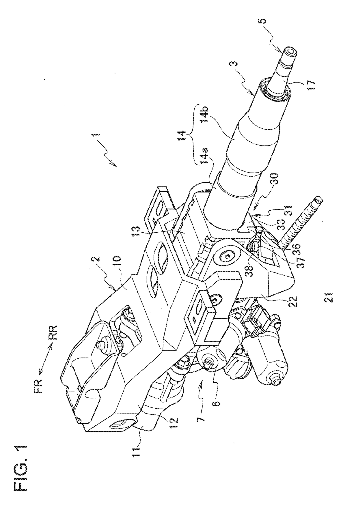
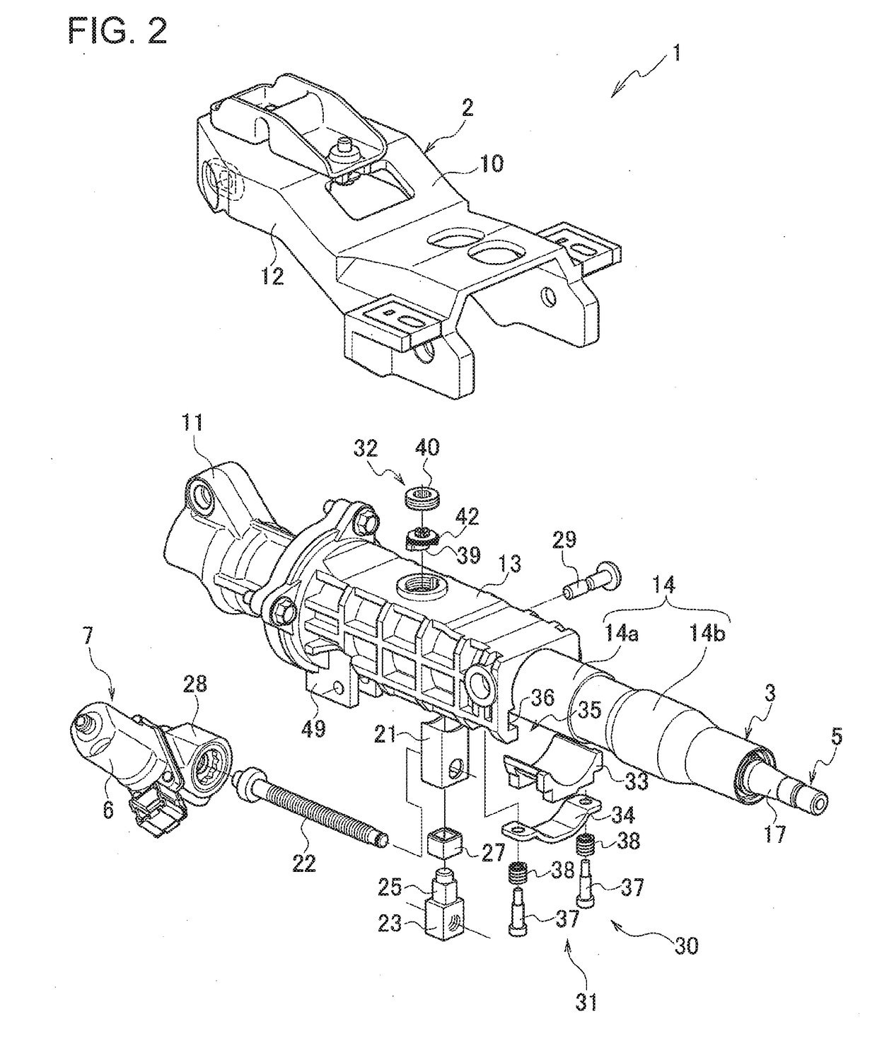
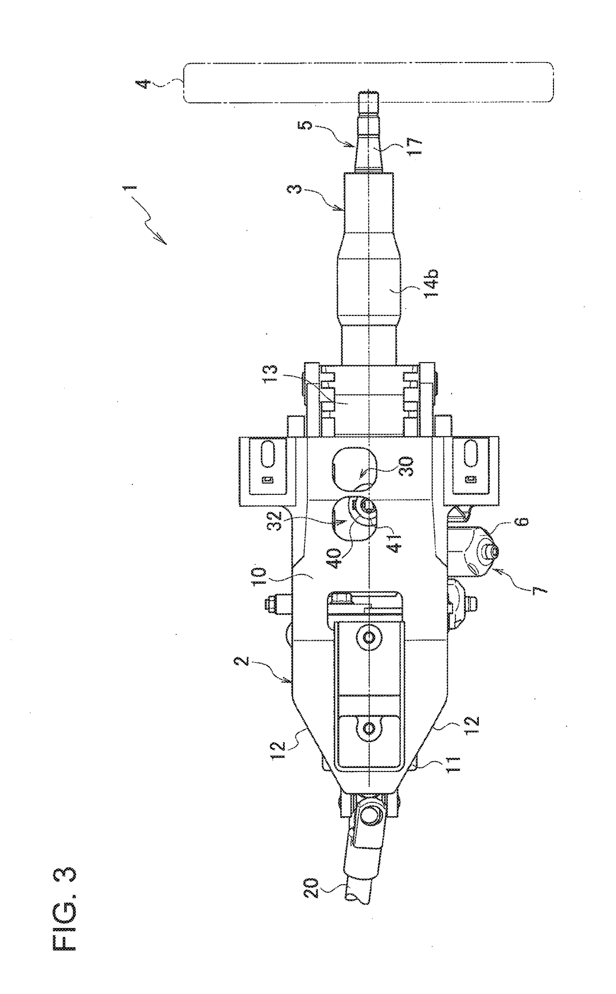
[0024]As illustrated in FIGS. 1 to 4, an electric steering column apparatus 1 includes a vehicle-body mounting bracket 2 fixed to the vehicle body and a steering column 3 swingably supported by the vehicle-body mounting bracket 2 in the vehicle up-down direction.

[0025]The electric steering column apparatus 1 also includes a steering shaft 5 rotatably supported by the steering column 3 and having a rear end to which a steering wheel 4 (see FIG. 3) is connected and a telescopic mechanism 7 driven by an electric motor 6.

[0026]The vehicle-body mounting bracket 2 integrally has a bracket body 10 and a pair of side walls 12, 12 extending downward from the bracket body 10 and disposed on both left and right sides of a swing support portion (front end s...


PUM


Abstract

An electric steering column apparatus includes a pressing mechanism for reducing the play between an outer jacket and an inner jacket. A pressing mechanism has a first pressing portion disposed on the outer jacket and pressing a lower surface of the inner jacket upward and a second pressing portion disposed on an axially front end side of the outer jacket and pressing an upper surface of the inner jacket downward. A tubular member housing a telescopic nut is disposed between the first pressing portion and the second pressing portion in an axial direction so as to face the second pressing portion in an up-down direction and fixed to the lower surface of the inner jacket.

Description

CROSS REFERENCE TO RELATED APPLICATION[0001]The present application is based on, and claims priority from Japanese Patent Application No. 2017-163050, filed Aug. 28, 2017; and 2017-163048, filed Aug. 28, 2017, the disclosure of which is hereby incorporated by reference herein in its entirety.TECHNICAL FIELD[0002]The present invention relates to electric steering column apparatuses.BACKGROUND ART[0003]Electric steering column apparatuses have been publicly known conventionally (for example, see Patent Literature 1: Japanese Patent Application Publication No. 2010-83392, Patent Literature 2: Japanese Patent Application Publication No. 2014-231288).[0004]One of the electric steering column apparatuses of this kind includes a steering column supported on the vehicle body, a steering shaft rotatably supported by the steering column, and a telescopic mechanism driven by an electric motor. In such an electric steering column apparatus, the steering column has an outer jacket and an inner j...

Claims


Application Information

Patent Timeline
IPC IPC(8): B62D1/181B62D1/185F16H25/20
CPCB62D1/181B62D1/185F16H25/20
Inventor INOUE, KYOICHIMIYAGI, TAKESHITERADA, DAISUKEOHASHI, TOMOYA
Owner FUJI KIKO CO LTD
Learn More