Magnetic shielding apparatus and biomagnetism measuring device
a magnetic shielding apparatus and biomagnetism technology, applied in the field of magnetic shielding apparatus, can solve the problems of deteriorating the magnetic shielding factor of the cylindrical magnetic shielding apparatus, limited space where the apparatus can be installed, and high cost, and achieve excellent workability and operability, and high sensitivity.
- Summary
- Abstract
- Description
- Claims
- Application Information
AI Technical Summary
Benefits of technology
Problems solved by technology
Method used
Image
Examples
first embodiment
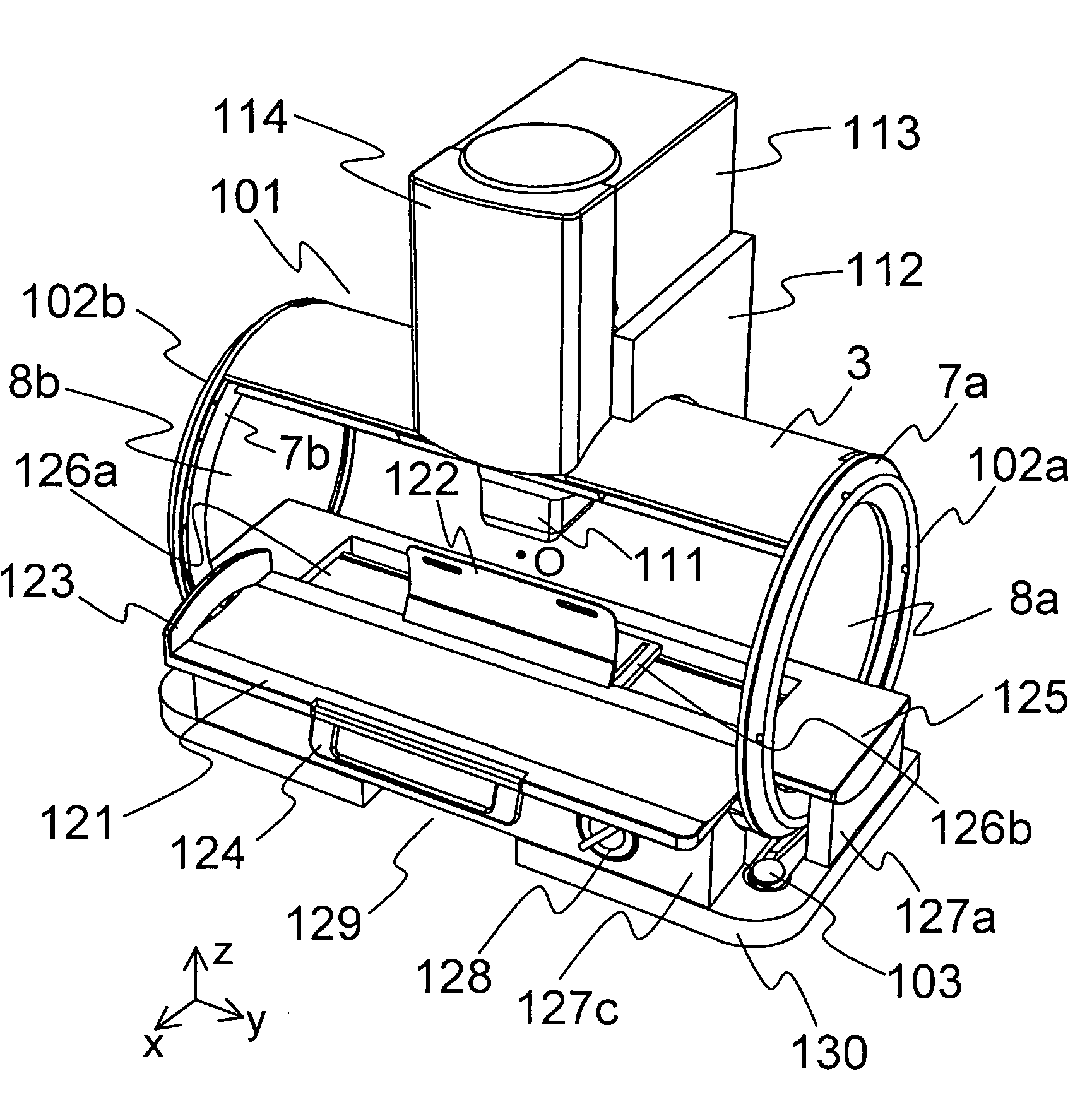
[0351] FIGS. 29 to 59 show a cardiac magnetic field measuring device equivalent to a first embodiment. FIG. 29 is an outside drawing showing the device, FIG. 30 is a block diagram showing the device, FIG. 31 shows a principle of measurement, FIGS. 32 to 48 are structural drawings showing the details of each device, FIGS. 49 to 54 show used states, FIGS. 55 to 58 are explanatory drawings for explaining a positioning device for positioning a subject, and FIGS. 62A to 62C show another combination.
[0352] First, referring to FIGS. 29 and 30, the schematic structure of the cardiac magnetic field measuring device equivalent to this embodiment will be described. FIG. 29 is an outside drawing showing the cardiac magnetic field measuring device. FIG. 30 is a block diagram showing the cardiac magnetic field measuring device.
[0353] As shown in FIGS. 29 and 30, the cardiac magnetic field measuring device includes a gantry 200 for holding a measuring part 100 provided with a fluxmeter (hereinaf...
second embodiment
[0510] Next, referring to FIGS. 60 to 62, the inside of a magnetic shield 300 will be described. FIGS. 60A to 60E are explanatory drawings showing the inside of the magnetic shield, FIG. 60A is a schematic sectional view, and FIGS. 60B to 60E show patterns on inner walls. FIGS. 61A and 61B are explanatory drawings showing a state in which an opening / closing body 304 is open, FIG. 61A is a schematic sectional view, and FIG. 61B shows a pattern on an inner wall viewed from the outside. FIGS. 62A to 62C are explanatory drawings showing a state in which the opening / closing body 304 is closed, FIGS. 62A and 62B are schematic sectional views, and FIG. 62C shows a pattern on the inner wall viewed inside shielded space.
[0511] First, referring to FIGS. 60A to 60E, rough structure in this embodiment will be described. In this embodiment, basic structure shown in FIGS. 60A to 60E is the similar structure to that in the first embodiment. This embodiment is greatly characterized in that a cardi...
third embodiment
[0520] Next, referring to FIGS. 63 to 65, a cardiac magnetic field measuring device equivalent to a third embodiment will be described. FIGS. 63A and 63B are perspective views showing the appearance of the cardiac magnetic field measuring device equivalent to the embodiment, FIG. 63A is the perspective view showing a state in which the opening / closing body 304 is open and FIG. 62B is the perspective view showing the opening / closing of the opening / closing body 304. FIGS. 64A to 64F are outside drawings showing the cardiac magnetic field measuring device, FIG. 64A is a plan, FIG. 64B is a bottom view, FIG. 64C is a front view, FIG. 64D is a right side view, FIG. 64E is a back view, and FIG. 64F is a left side view. FIG. 65 is a schematic sectional view showing the cardiac magnetic field measuring device.
[0521] This embodiment is first characterized in that a cylindrical holding body 350 is provided on one side of a cylindrical magnetic shield 300 to be overhung type structure and opp...
PUM
 Abstract
Description
Claims
Application Information
 - R&D
- Intellectual Property
- Life Sciences
- Materials
- Tech Scout
- Unparalleled Data Quality
- Higher Quality Content
- 60% Fewer Hallucinations
Browse by: Latest US Patents, China's latest patents, Technical Efficacy Thesaurus, Application Domain, Technology Topic, Popular Technical Reports.
© 2025 PatSnap. All rights reserved.Legal|Privacy policy|Modern Slavery Act Transparency Statement|Sitemap|About US| Contact US: help@patsnap.com


