
Surgical positioning and holding device

a technology of which is applied in the field of surgical positioning and holding device, can solve the problems of machining tool advancemen

Inactive Publication Date: 2006-03-09
AESCULAP AG
View PDF21 Cites 78 Cited by
  • Summary
  • Abstract
  • Description
  • Claims
  • Application Information

AI Technical Summary

Benefits of technology

[0008] To ensure a particularly secure hold of the device on the bone to be worked on, it is advantageous for a second fastening element to be provided for fixation to the bone to be worked on and for the second fastening element to be guided and / or held on the platform.
[0036] It is advantageous for the fourth axis of rotation defined by the guide to extend at right angles to the first axis of rotation. This arrangement makes it possible to work on a bone with a machining tool from the front, for example, with a face milling cutter. In this way, a surface concentric with the first axis of rotation may be made.

Problems solved by technology

Herein it is disadvantageous that the machining tool has to be advanced towards the bone to be machined from the front because this makes complete opening of the damaged joint necessary.

Method used


Image

  • Surgical positioning and holding device
  • Surgical positioning and holding device
  • Surgical positioning and holding device

Examples


Embodiment Construction

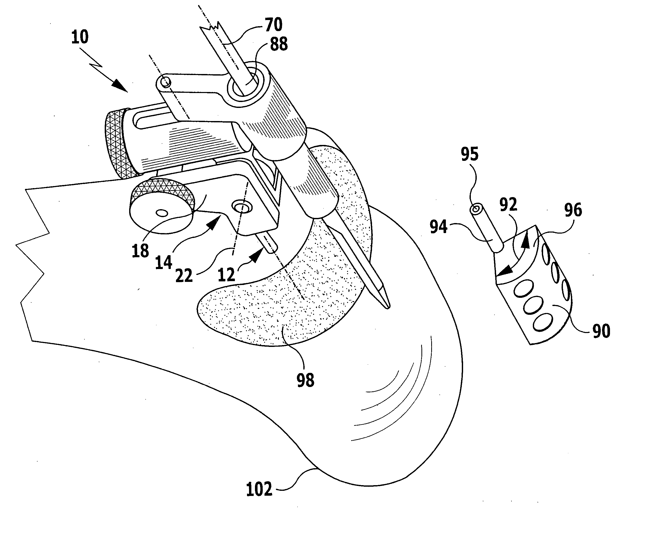
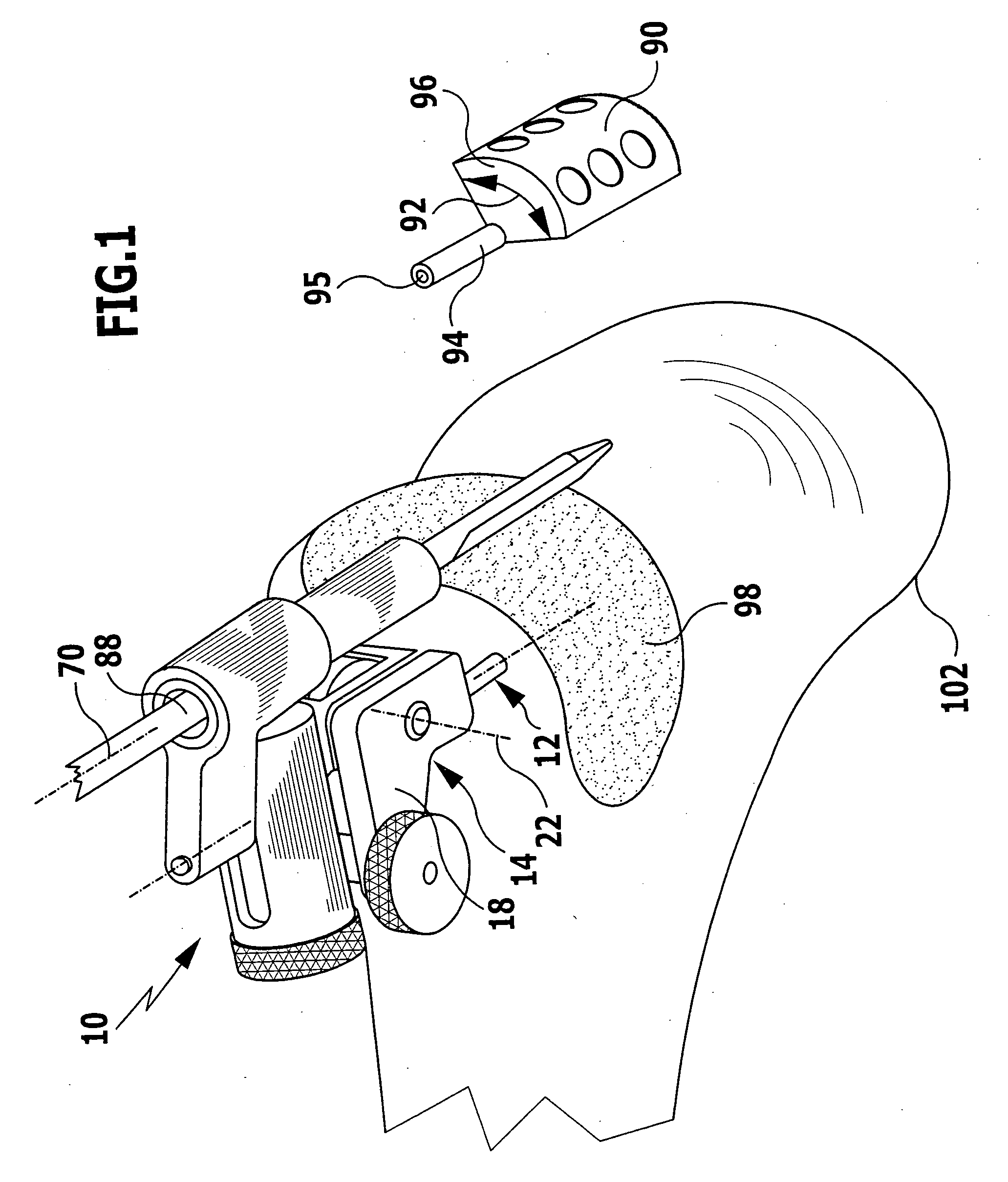
[0048]FIG. 1 shows a surgical positioning and holding device according to the invention, which comprises an aligning instrument generally designated by reference numeral 10 and two bone pins 12.

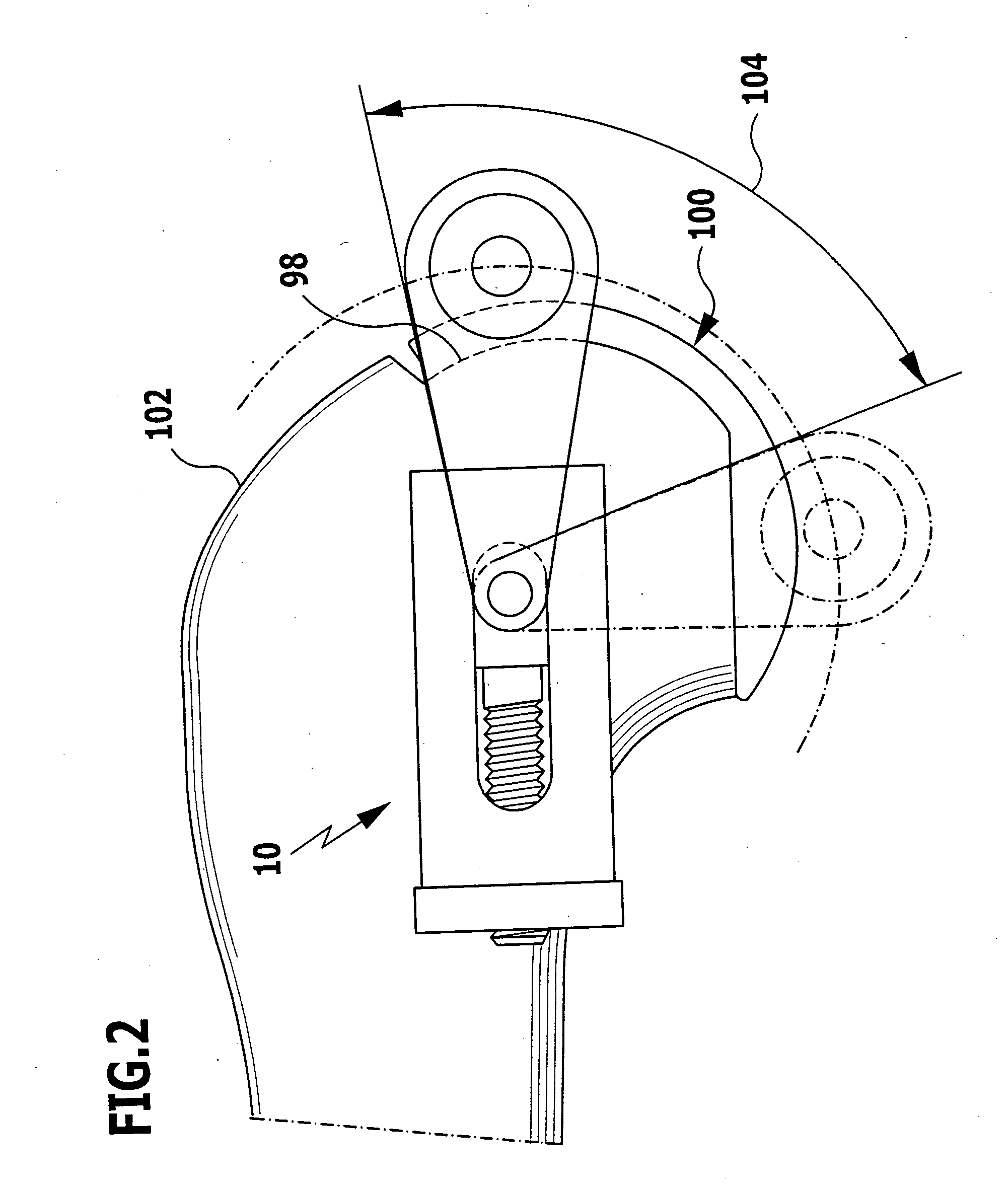
[0049] The aligning instrument 10 comprises two frame parts mounted for pivotal movement relative to each other, namely a holding frame 14 connected to the bone pins 12 and a bearing frame 16. The holding frame 14 comprises two flat, L-shaped side walls 18 which are arranged parallel to each other and are connected to each other by a connecting plate 20. The substantially L-shaped bearing frame 16 is mounted between the side walls 18 so as to be pivotable about a pivot axis 22 relative to the holding frame 14.

[0050] The pivot axis 22 is defined by a threaded spindle 24 of a spindle drive generally designated by reference numeral 25. The threaded spindle 24 is rotationally fixedly connected to the side walls 18 and is provided with an external thread in an area between the two side walls 18....


PUM


Abstract

In order to improve a surgical positioning and holding device for positioning and holding a guide for a surgical machining tool, with at least one fastening element for fixation to a bone to be machined and with a platform held on the at least one fastening element so as to hold the guide, so that anchoring surfaces may be prepared in a simple manner and with a high degree of precision on a bone to be machined, it is proposed that the guide be mounted for rotation about a first axis of rotation and be designed such that at least one surface concentric with the first axis of rotation may be prepared with the machining tool guided in or held on the guide.

Description

[0001] This application is a continuation of international application number PCT / EP2004 / 001347 filed on Feb. 13, 2004. [0002] The present disclosure relates to the subject matter disclosed in international application number PCT / EP2004 / 001347 of Feb. 13, 2004 and German application number 103 09 987.5 of Feb. 28, 2003, which are incorporated herein by reference in their entirety and for all purposes.BACKGROUND OF THE INVENTION [0003] The present invention relates to a surgical positioning and holding device for positioning and holding a guide for a surgical machining tool, with at least one fastening element for fixation to a bone to be machined and with a platform held on the at least one fastening element so as to hold the guide mounted for rotation about a first axis of rotation. [0004] Such devices are used, for example, in operations on joints, in which parts of a damaged joint are replaced by artificial joint components. For this purpose, the device is fixed with the at least...

Claims


Application Information

Patent Timeline
Patent Type & Authority Applications(United States)
IPC IPC(8): A61F5/00A61B17/15A61B17/17
CPCA61B17/154A61B17/1764A61B17/155
Inventor HAGEN, THOMASREICH, JAN
Owner AESCULAP AG
Learn More