Waterproof infrared ear thermometer

a technology of infrared ear thermometers and ear thermometers, which is applied in the field of clinical thermometers, can solve the problems of difficult to wash, difficult to interfere with heat sources, and lack of waterproof function of current used ear thermometers, and achieve the effect of reducing hea

Inactive Publication Date: 2006-03-09
AMPLIFE CORP
View PDF7 Cites 12 Cited by
  • Summary
  • Abstract
  • Description
  • Claims
  • Application Information

AI Technical Summary

Benefits of technology

[0007] Accordingly, the primary object of the present invention is to provide a waterproof infrared ear thermometer which comprises a casing containing the sensor head; a front end of the casing being a hollowed long tube; a sensor unit and a heat dissipating block being received in the casing; a front end of the sensor unit being a temperature sensing portion; an outer front ring of the temperature sensing portion having a forward protruded water-proof washer; and a front end of the casing being protruded with a stopper; the stopper being buckled in an inner edge of the water-proof washer so as to achieve the affect of preventing liquid from flowing into the sensor head. A heat dissipating block is firmly secured between the casing and the sensor unit so as to reduce heat to be transferred to the sensor unit. An infrared sensor and an environmental temperature sensor are installed in the temperature sensing portion.

Problems solved by technology

Since the ear thermometer is near the heat source of the brain so that the heat source is difficult to be interfered.
However the current used ear thermometers have no waterproof function.
This kind of prior art ear thermometer has no waterproof design so that it is difficult to be washed.
Not only more work is necessary and when it is used for a longer time, the cost of the cover is also a burden.
Furthermore, the structure of the sensor head 90 with two waterproof washers 93 is complicated.
Thereby although the prior art waterproof ear thermometer has the function of waterproof, but it has a complicated structure.

Method used


Image

  • Waterproof infrared ear thermometer
  • Waterproof infrared ear thermometer
  • Waterproof infrared ear thermometer

Examples


Embodiment Construction

[0013] In order that those skilled in the art can further understand the present invention, a description will be described in the following in details. However, these descriptions and the appended drawings are only used to cause those skilled in the art to understand the objects, features, and characteristics of the present invention, but not to be used to confine the scope and spirit of the present invention defined in the appended claims.

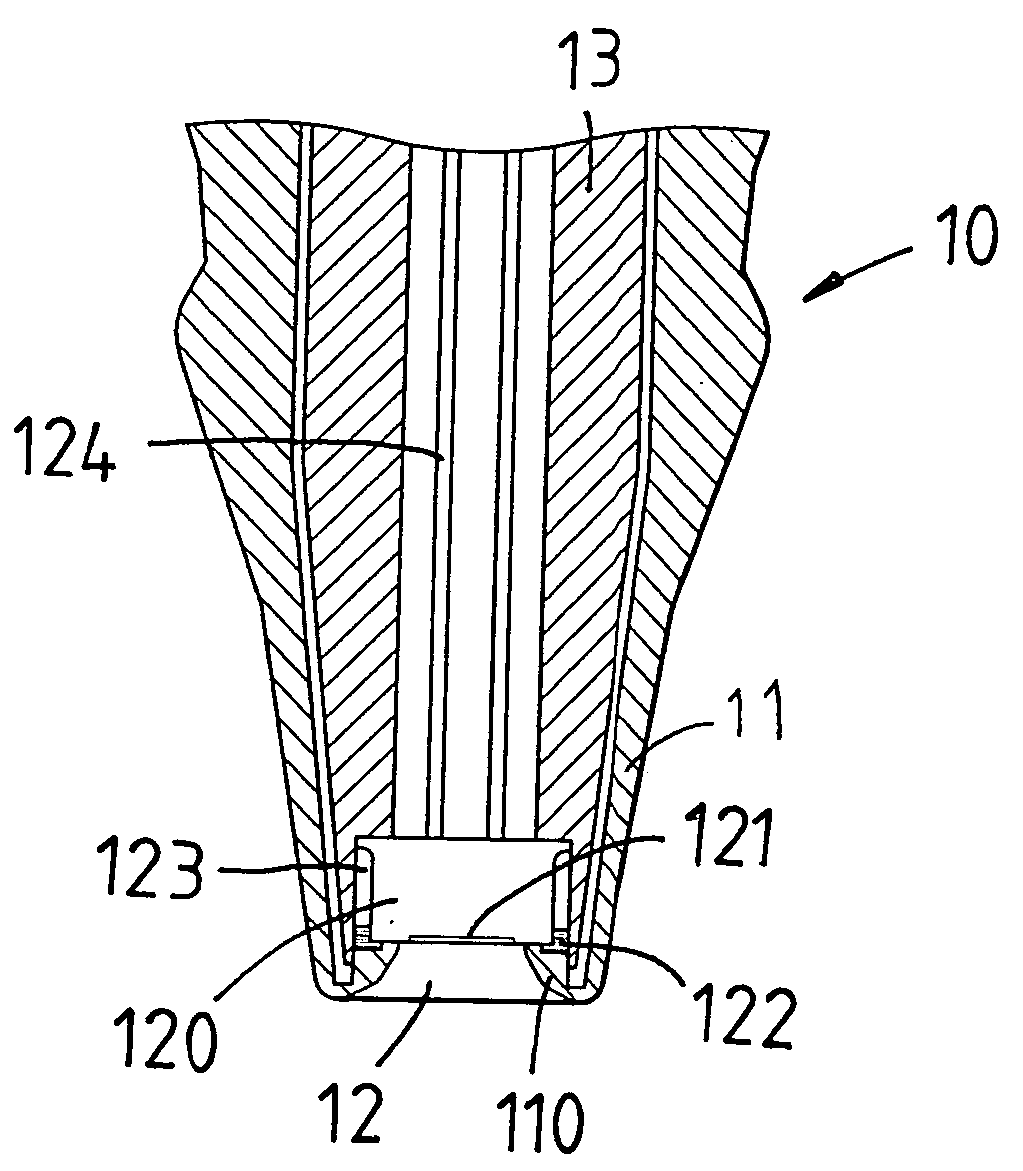
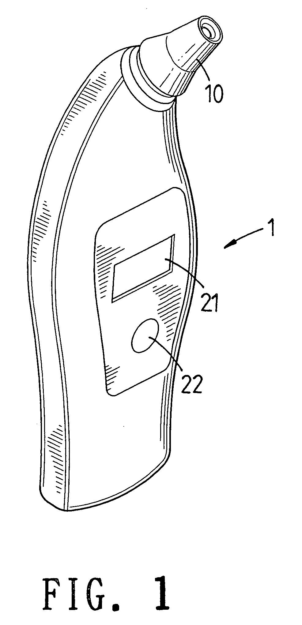
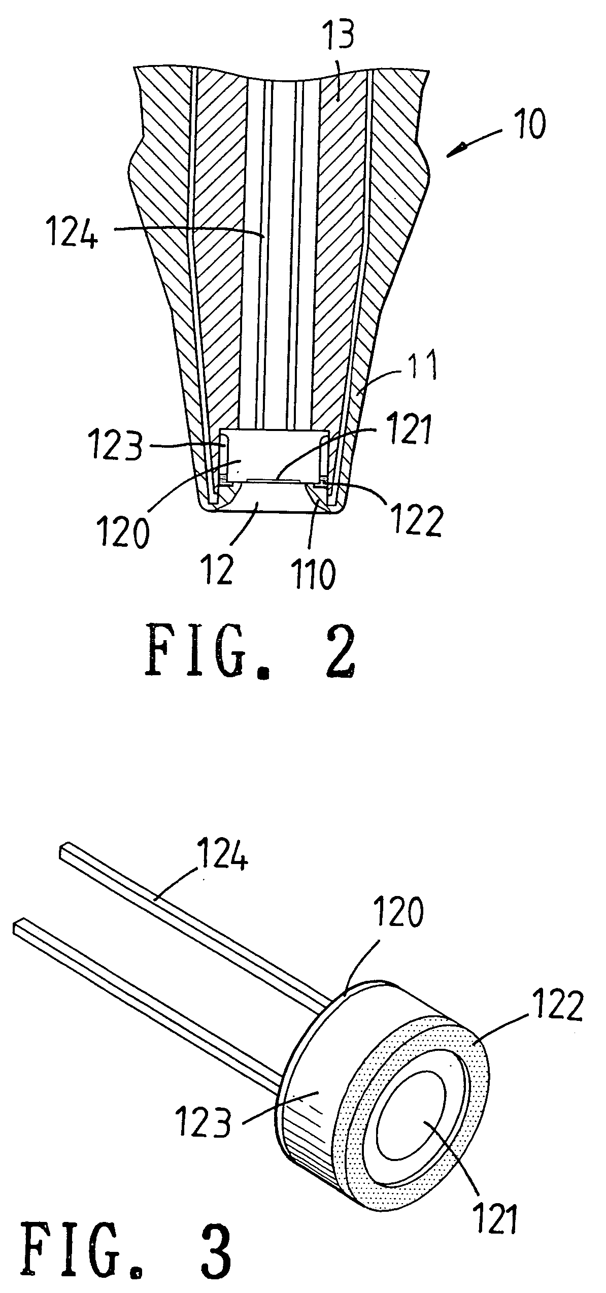
[0014] With reference to FIGS. 1 to 3, the structure of the present invention is illustrated. The waterproof infrared ear thermometer comprise the following elements.

[0015] A body 1 has a sensor head 10, a display 21 and a control button 22 for switching and controlling. The sensor head 10 serves to insert into the cochlea of one to be measured for receiving infrared from a heat source. An operator unit (not shown) in the body 1 serves to calculate the temperature and then the temperature value is displaced on the display 21. However the way fo...


PUM


Abstract

A waterproof infrared ear thermometer comprises a casing containing a sensor head; a front end of the casing being a hollowed long tube; a sensor unit and a heat dissipating block being received in the casing; a front end of the sensor unit being a temperature sensing portion; an outer front ring of the temperature sensing portion having a forward protruded water-proof washer; and a front end of the casing being protruded with a stopper; the stopper being buckled in an inner edge of the water-proof washer so as to achieve the affect of preventing liquid from flowing into the sensor head. A heat dissipating block is firmly secured between the casing and the sensor unit so as to reduce heat to be transferred to the sensor unit. An infrared sensor and an environmental temperature sensor are installed in the temperature sensing portion.

Description

FIELD OF THE INVENTION [0001] The present invention relates to clinical thermometers, and particularly to a waterproof infrared ear thermometer. Thereby when the ear thermometer is wiped, no water will permeate into the structure. BACKGROUND OF THE INVENTION [0002] Ear thermometers serve to measure the infrared radiation of the interior of the ear so as to get the temperature of the user. Since the ear thermometer is near the heat source of the brain so that the heat source is difficult to be interfered. Thereby using infrared light to measure temperature is not only accurate, but also time-efficient. Thereby the ear thermometers have become a main trend of clinical thermometers. However the current used ear thermometers have no waterproof function. Thus a cover is necessary to be used therewith so that the ear thermometer will not be polluted by the dirt in the ear. This is more important when several uses use the ear thermometer in common. [0003] In the prior art, a sensor unit is...

Claims


Application Information

Patent Timeline
IPC IPC(8): G01J5/00G01K1/00
CPCG01J5/04G01J5/045G01J2005/068G01J5/049G01J5/06G01J5/048G01J5/064
Inventor LEE, YUNG-KU
Owner AMPLIFE CORP
Why Eureka
Try Eureka