
Picture color tone controlling method and apparatus

a color tone and control method technology, applied in the field of picture color tone control methods and apparatuses, can solve the problems of high cost of spectrometer, large amount of paper loss after printing process, and inability of spectrometer to follow up the measurement object, so as to reduce the cost, appropriately perform color tone control, and eliminate positional displacement.

Inactive Publication Date: 2006-03-09
MITSUBISHI HEAVY IND LTD
View PDF5 Cites 26 Cited by
  • Summary
  • Abstract
  • Description
  • Claims
  • Application Information

AI Technical Summary

Benefits of technology

[0026] It is an object of the present invention to provide a picture color tone controlling method and apparatus for a printing press which can readily and rapidly eliminate a positional displacement between a plate making image and an actual machine image and also a positional displacement which appears as time passes and can appropriately perform color tone control in which an IRGB densitometer which requires a lower cost than a spectrometer is used.

Problems solved by technology

The spectrometer requires a high cost.
Further, where an object of measurement (in this instance, a printing sheet) moves at a very high speed as in the case of a rotary press for newspapers, the spectrometer cannot follow up the measurement object because of the processing capacity thereof.
Further, in the method described above, since the color tone control is started after an OK sheet is printed, a great amount of paper loss appears after the printing process is started until the OK sheet is printed.
Therefore, where the image line ratio of the picture in a key zone is low, a measurement error of the spectrometer increases and the control is likely to be rendered instable.
If such a positional displacement as described above appears, then since a noticed pixel on the plate making image and a noticed pixel on the actual machine image become different from each other, picture color tone control cannot be performed appropriately.
However, if the movement of the densitometer 1 or the adjustment of the pulse timing of the rotary encoder is performed by manual operation, then it is difficult to eliminate the positional displacement with a high degree of accuracy.
Further, if it is tried to perform the adjustment with a high degree of accuracy, then much time is required and paper loss before the control is started increases.
Furthermore, even if positioning can be performed appropriately upon starting of the control, during operation, a positional displacement sometimes occurs because of a variation of the tension of the printing paper or because of appearance of meandering on the printing paper as time passes.
However, it is difficult to cope with the positional displacement just described.

Method used


Image

  • Picture color tone controlling method and apparatus
  • Picture color tone controlling method and apparatus
  • Picture color tone controlling method and apparatus

Examples


first embodiment

A. First Embodiment

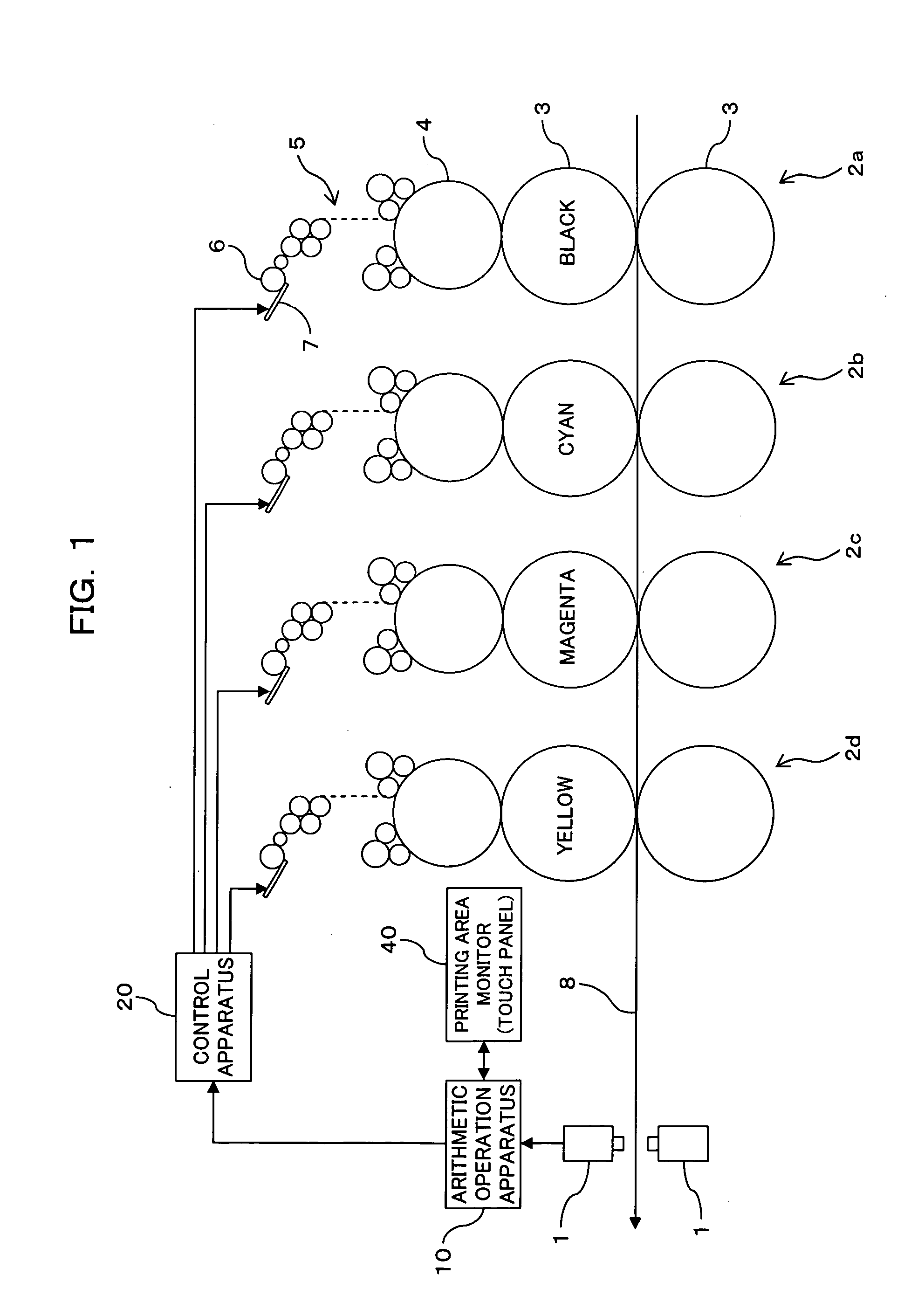
[0062]FIG. 1 shows a general configuration of an offset rotary press for newspapers according to a first embodiment of the present invention. The offset rotary press for newspapers of the present embodiment is a double-sided printing press for multi-color printing and includes printing units 2a, 2b, 2c and 2d disposed for different ink colors [black (k), cyan (c), magenta (m) and yellow (y)] along a transport path of a printing sheet 8. In the present embodiment, each of the printing units 2a, 2b, 2c and 2d includes an ink supplying apparatus of the ink key type which includes a plurality of ink keys 7 and an ink fountain roller 6. In the ink supplying apparatus of the type described, the ink supplying amount can be adjusted by the gap amount (the gap amount is hereinafter referred to as ink key opening) of each of the ink keys 7 from the ink fountain roller 6. The ink keys 7 are juxtaposed in the printing widthwise direction, and the ink supplying amount can be a...

second embodiment

B. Second Embodiment

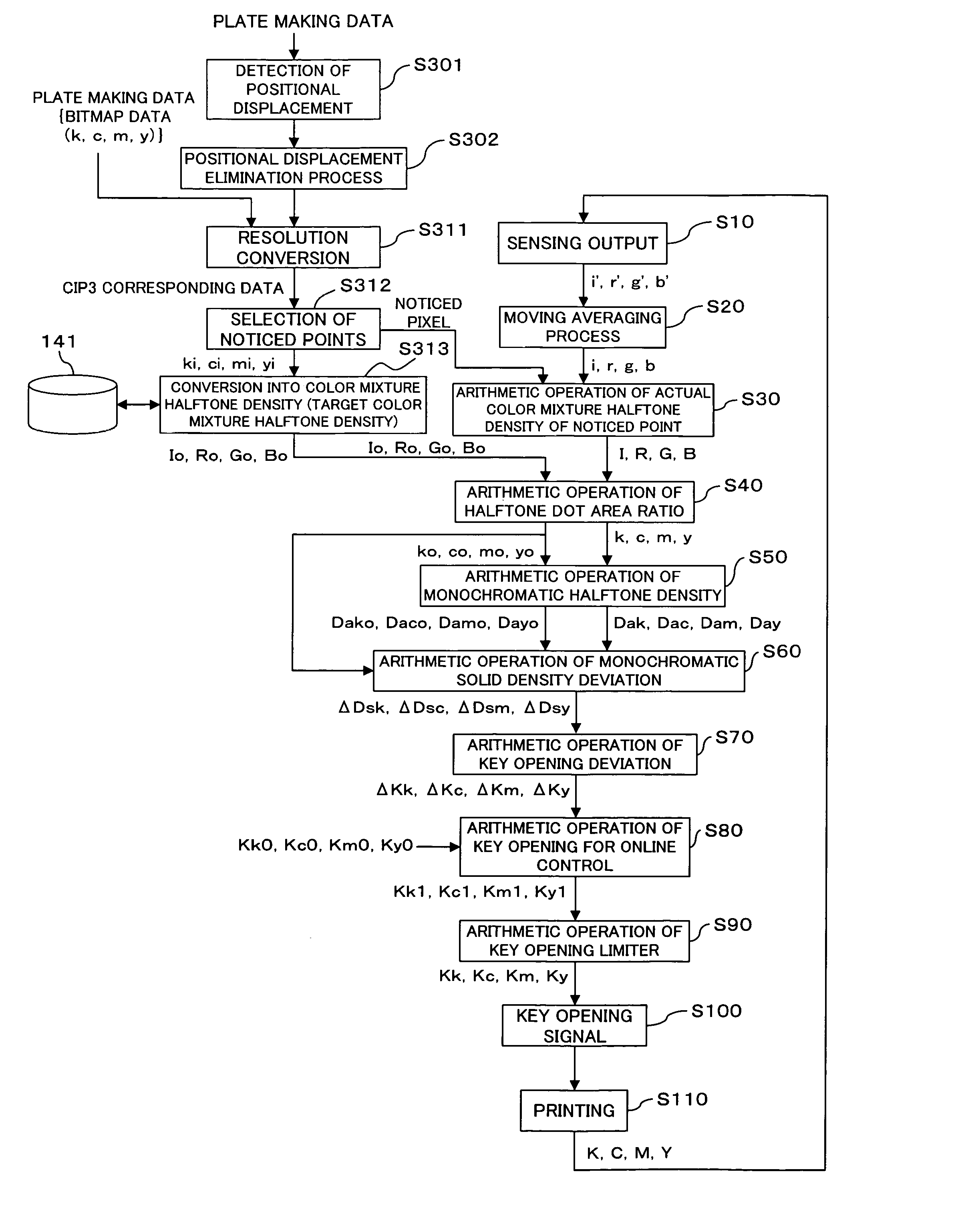
[0095] A second embodiment of the present invention is described with reference to FIG. 7. Also the present embodiment detects a positional displacement between a plate making picture position and an actual picture position and moves the plate making picture position so as to eliminate the positional displacement, similarly to the first embodiment.

[0096] It is assumed that, also in the present embodiment, printing data of page information for a newspaper transmitted in the form of bitmap data from the head office of a newspaper company to a printing factory are inputted similarly as in the first embodiment. However, in the present embodiment, as a first difference from the first embodiment, also an ICC profile of an inputting apparatus by which color information of the page has been produced is transmitted in addition to the bitmap data of the page information. At step S321, the bitmap data are converted into low resolution data corresponding to CIP3 data accord...

third embodiment

[0102] A third embodiment of the present invention is described with reference to FIG. 8. The present embodiment proposes an auxiliary method for color tone control and can be applied additionally to both of the color control methods of the first and second embodiments. It is to be noted that, in the present third embodiment, a positional displacement between the plate making picture position and the actual picture position is detected and the plate making picture position is moved so that the positional displacement may be eliminated, similarly as in the first embodiment.

[0103] At step S401, the conversion table recorded in the database 141 is used to convert the target color mixture halftone densities Io, Ro, Go, Bo into color coordinate values (target color coordinate values) (this function is defined as target color coordinate value arithmetic operation means). At step S402, the conversion table is used similarly to convert the actual color mixture halftone densities I, R, G, B...


PUM


Abstract

A picture color tone controlling method and apparatus for a printing press is disclosed which can readily and rapidly eliminate a positional displacement between a plate making image and an actual machine image and can appropriately perform color tone control in which an IRGB densitometer is used. A plate making picture position obtained from plate making data is moved so that a positional displacement between the plate making picture position and an actual picture position obtained from a result of actual printing. A target color mixture halftone density for each ink supplying unit width when a printing picture is divided with an ink supplying unit width of an ink supplying apparatus is set. An IRGB densitometer is used to measure the actual color mixture halftone density for each ink supplying unit width of an actually printed sheet obtained by printing. The color mixture halftone densities are individually converted into halftone dot area ratios and further into monochromatic halftone densities. Then, the Yule-Nielsen expression or the like is used to determine a solid density deviation corresponding to a deviation between the target monochromatic halftone density and the actual monochromatic halftone density, and the ink supplying amount is adjusted for each ink supplying unit width in response to the solid density deviation.

Description

BACKGROUND OF THE INVENTION [0001] 1) Field of the Invention [0002] This invention relates to a picture color tone controlling method and apparatus for a printing press, and more particularly to a picture color tone controlling method and apparatus for controlling the color tone using an IRGB densitometer. [0003] 2) Description of the Related Art [0004] Various techniques have been proposed as a technique for color tone control of a picture of a printing press. [0005] For example, in techniques disclosed in Japanese Patent Laid-Open No. 2001-18364 (hereinafter referred to as Patent Document 1) and Japanese Patent Laid-Open No. 2001-47605 (hereinafter referred to as Patent Document 2), color tone control is performed in such a procedure as described below. [0006] First, a spectral reflectance of a picture printed by printing units of different colors is measured by a spectrometer. Then, the spectral reflectance (average spectral reflectance in an overall key zone) is calculated for e...

Claims


Application Information

Patent Timeline
IPC IPC(8): B41C1/04
CPCB41F31/045B41F33/0045G01J3/50G01J3/463B41P2233/51
Inventor OZAKI, IKUOTAKEMOTO, SYUUICHITASAKA, NORIFUMI
Owner MITSUBISHI HEAVY IND LTD
Learn More