
Monitor supporting and rotating structure

a technology for rotating structures and monitors, applied in the field of flat panel display supporting and rotating structures, can solve the problems of large volume of conventional supporting stands, inconvenient consumers, and large space occupation of conventional lcd supporting stands, and achieve the effect of convenient monitor mobility and efficient space occupation

Inactive Publication Date: 2006-03-09
SHUTTLE
View PDF7 Cites 75 Cited by
  • Summary
  • Abstract
  • Description
  • Claims
  • Application Information

AI Technical Summary

Benefits of technology

[0005] The present invention provides a monitor supporting and rotating structure which is utilized to prop up a flat panel display. The monitor supporting and rotating structure both facilitates the mobility of the monitor and its efficient usage of space.
[0006] The monitor supporting and rotating structure which is provided by the present invention includes a supporting stand and a rotary member pivotally attached to the top of the supporting stand. The rotary member has a fixing plate which is screwed onto the rear of a monitor. A rotating plate is pivotally connected to both the fixing plate and the supporting stand. The fixing plate is capable of left-handed, right-handed, forward, and backward rotation, relative to the rotating plate. The supporting stand is capable of being propped outward. It is by propping the supporting stand away from the display that the display is oriented and erected above a plane. Further, the rotary member enables the display to perform left-handed, right-handed, forward, or backward rotations.

Problems solved by technology

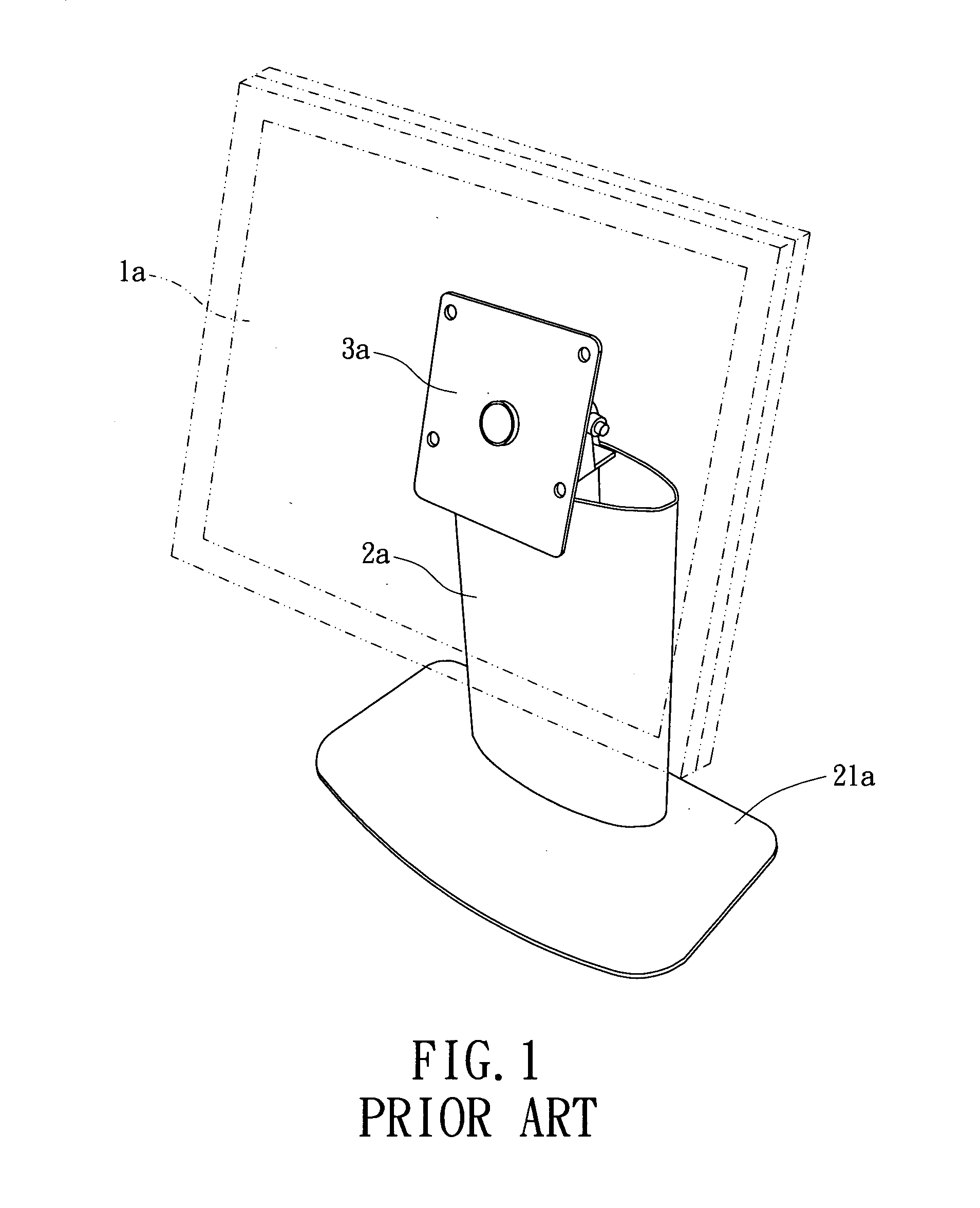
However, the supporting stand 2a is an attachment of the display 1a. A consumer must personally assemble the supporting stand 2a onto the display 1a. Further, the volume of a conventional supporting stand is large and takes up a great deal of space.
The conventional LCD supporting stand is, therefore, inconvenient for consumers.

Method used


Image

  • Monitor supporting and rotating structure
  • Monitor supporting and rotating structure
  • Monitor supporting and rotating structure

Examples


Embodiment Construction

[0016] Reference will now be made in detail to the preferred embodiments of the present invention, examples of which are illustrated in the accompanying drawings. Wherever possible, the same reference numbers are used in the drawings and descriptions to refer to the same or like parts.

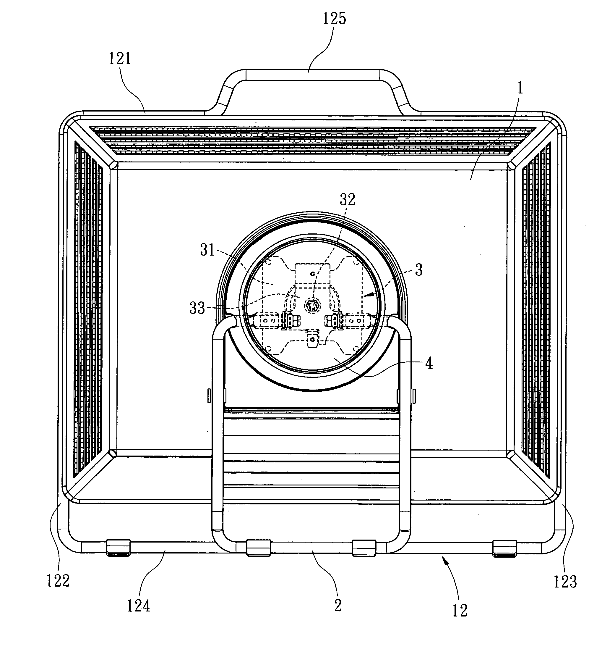
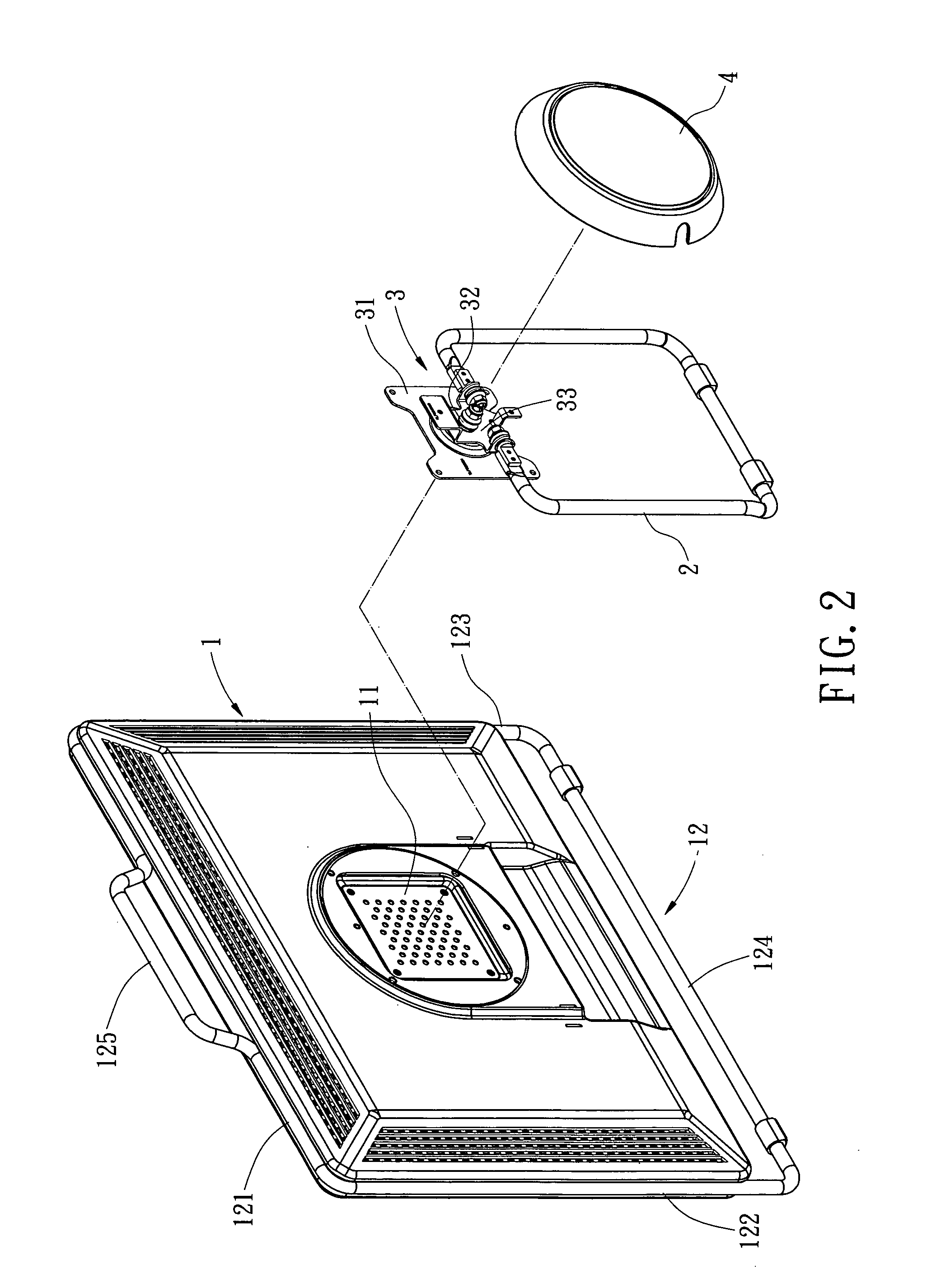
[0017] Referring to FIGS. 2 and 3, the present invention is applied to a LCD monitor in order to erect the LCD 1 above a plane, and to enable the LCD 1 to perform left-handed, right-handed, forward, or backward rotations. The monitor supporting and rotating structure includes a supporting stand 2 which has a hollow, approximately rectangle configuration, and a rotary member 3 which is pivotally connected to the top of the supporting stand 2.

[0018] The rotary member 3 includes a fixing plate 31, a pivotal axis 32, and a rotating plate 33. The fixing plate 31 is screwed onto a receptive space 11 of the LCD 1. By utilizing the pivotal axis 32, the rotating plate 33 is pivotally connected to the fixing p...


PUM


Abstract

A monitor supporting and rotating structure, by which a monitor is capable of being erected and rotated. The monitor supporting and rotating structure includes a supporting stand and a rotary member pivotally attached to the top of the supporting stand. The supporting stand is capable of being propped outward. It is by propping the supporting stand away from the display that the display is oriented and erected above a plane. Further, the rotary member enables the display to perform left-handed, right-handed, forward, or backward rotations. The monitor supporting and rotating structure both facilitates the mobility of the monitor and its efficient usage of space.

Description

BACKGROUND OF THE INVENTION [0001] The present invention relates in general to a monitor supporting and rotating structure, and more particularly, to a flat panel display supporting and rotating structure, by which a monitor is capable of being erected and rotated. [0002] In recent years, liquid crystal display (LCD) technology has progressed rapidly. This rapid progress has been fueled by the preference consumers have shown for the LCD, which is due, in large part, to the LCD's better image quality and space conservation. [0003] A conventional LCD monitor is shown in FIG. 1. The outer structure of a conventional LCD monitor includes a flat panel display 1a, a supporting stand 2a pivotally connected to the display 1a, and a rotatable fixing plate 3a which is installed onto the top of the supporting stand 2a. The supporting stand 2a has a base mount 21a which is installed beneath the bottom thereof in order to erect the supporting stand 2a. The rear of the display 1a is securely conn...

Claims


Application Information

Patent Timeline
IPC IPC(8): A47G29/00
CPCF16M11/00F16M11/10F16M2200/08F16M11/2021F16M13/005F16M11/105
Inventor CHEN, YIN-HUNG
Owner SHUTTLE
Learn More