Eureka AIR delivers breakthrough ideas for toughest innovation challenges, trusted by R&D personnel around the world.

Filter device used in a paint cup of a spraying gun

a filter device and spraying gun technology, which is applied in the direction of cartridge filters, filtration separation, separation processes, etc., can solve the problems of troublesome installation or removal of filters, user's need to wash filter meshes frequently, and relatively high manufacturing costs, so as to improve paint-filtering efficiency and simple structure , the effect of large filtering area

Inactive Publication Date: 2006-03-09
CHANG JEN CHIH
View PDF4 Cites 15 Cited by
  • Summary
  • Abstract
  • Description
  • Claims
  • Application Information

AI Technical Summary

Benefits of technology

"The present invention provides a filter device for a spraying gun. The filter is placed in the paint cup and has a large filtering area, enhanced efficiency. The filter mesh is designed to prevent jamming and can be easily detached for cleaning. The filter has a ventilating tube with a cap that prevents paint from flowing into it. The filter is securely attached to the paint cup and has a fixing section. The filter mesh is engaged with the bottom of the paint cup to prevent detachment. The filter device is simple in structure, low in manufacturing cost, and has improved market competition."

Problems solved by technology

It is uneasy to manufacture such filter so that the manufacturing cost is relatively high.
As a result, a user needs to frequently wash the filter mesh.
Furthermore, the filter 62 has a complicated structure so that it is quite troublesome to install or detach the filter 62.
Therefore, it is time-consuming to remove the impurities accumulating on the filter 62.
This leads to higher manufacturing cost.

Method used


Image

  • Filter device used in a paint cup of a spraying gun
  • Filter device used in a paint cup of a spraying gun
  • Filter device used in a paint cup of a spraying gun

Examples


Embodiment Construction

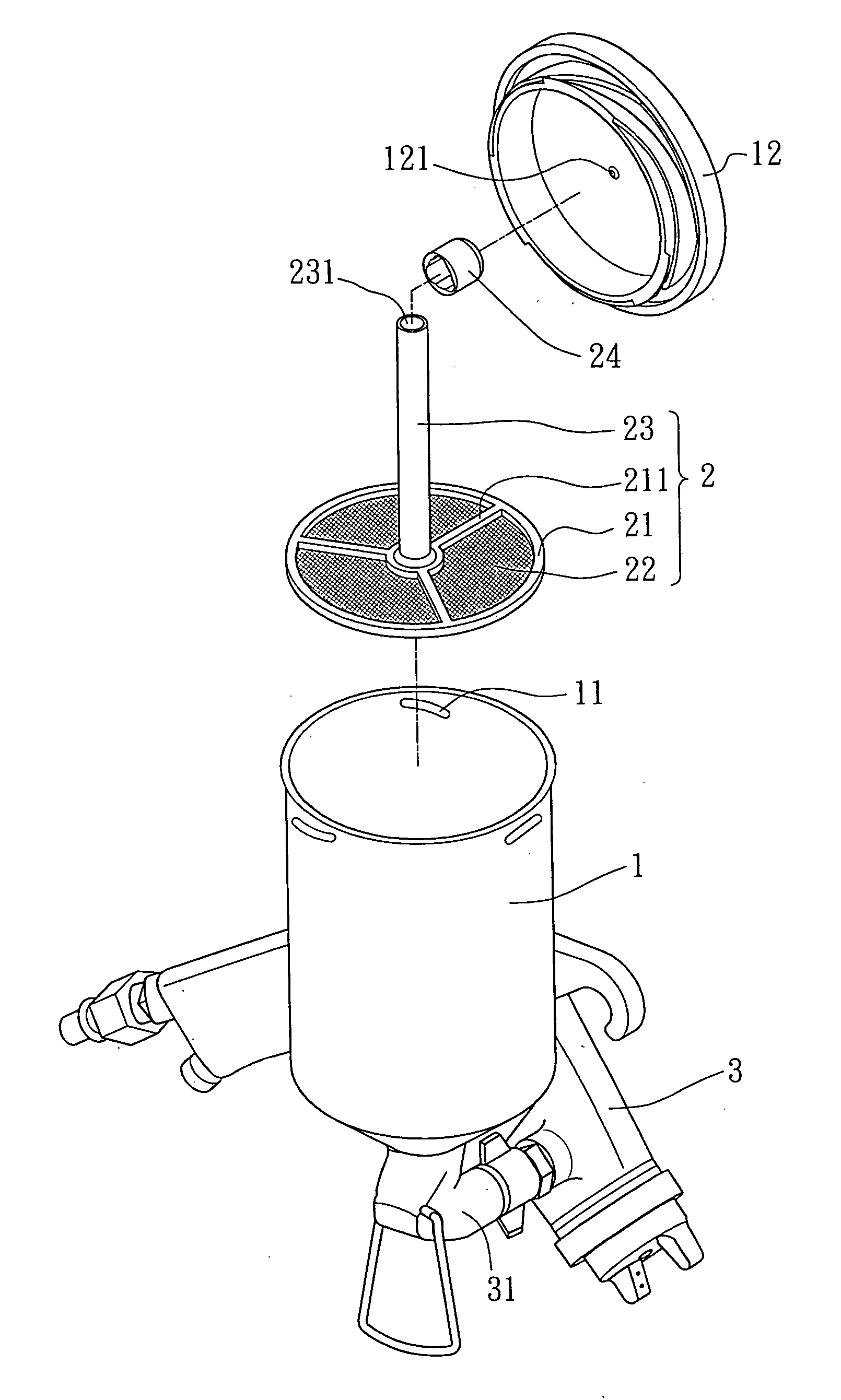
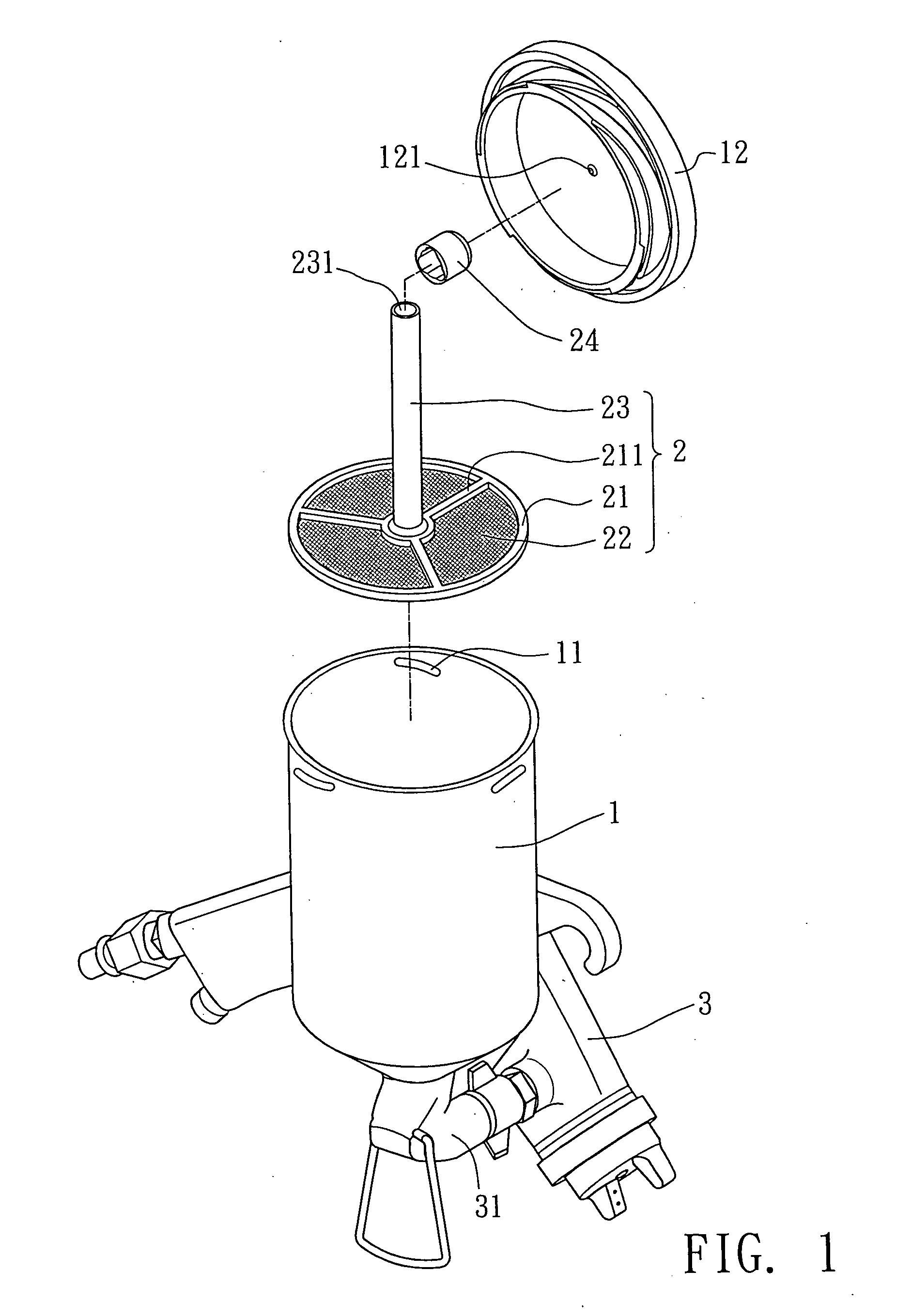
[0021] Please refer to FIGS. 1 and 6. The filter device used in the paint cup of the spraying gun of the present invention includes a filter 2 mounted in the paint cup body 1.

[0022] The opening of the paint cup body 1 is formed with several engaging sections 11 for engaging with a top cap 12 corresponding to the paint cup body 1. The top cap 12 is formed with a through hole 121. When the top cap 12 is mated with the paint cup body 1, the through hole 121 serves to remove the pressure in the paint cup body 1. The bottom of the paint cup body 1 is tapered into a conic shape for connecting with a connecting tube 31 for connecting with the spraying gun 3. An adjoining section between the inner face of the conic bottom of the paint cup body 1 and the inner face of the wall of the paint cup body 1 is formed as a fixing section 13 for fixing the filter 2.

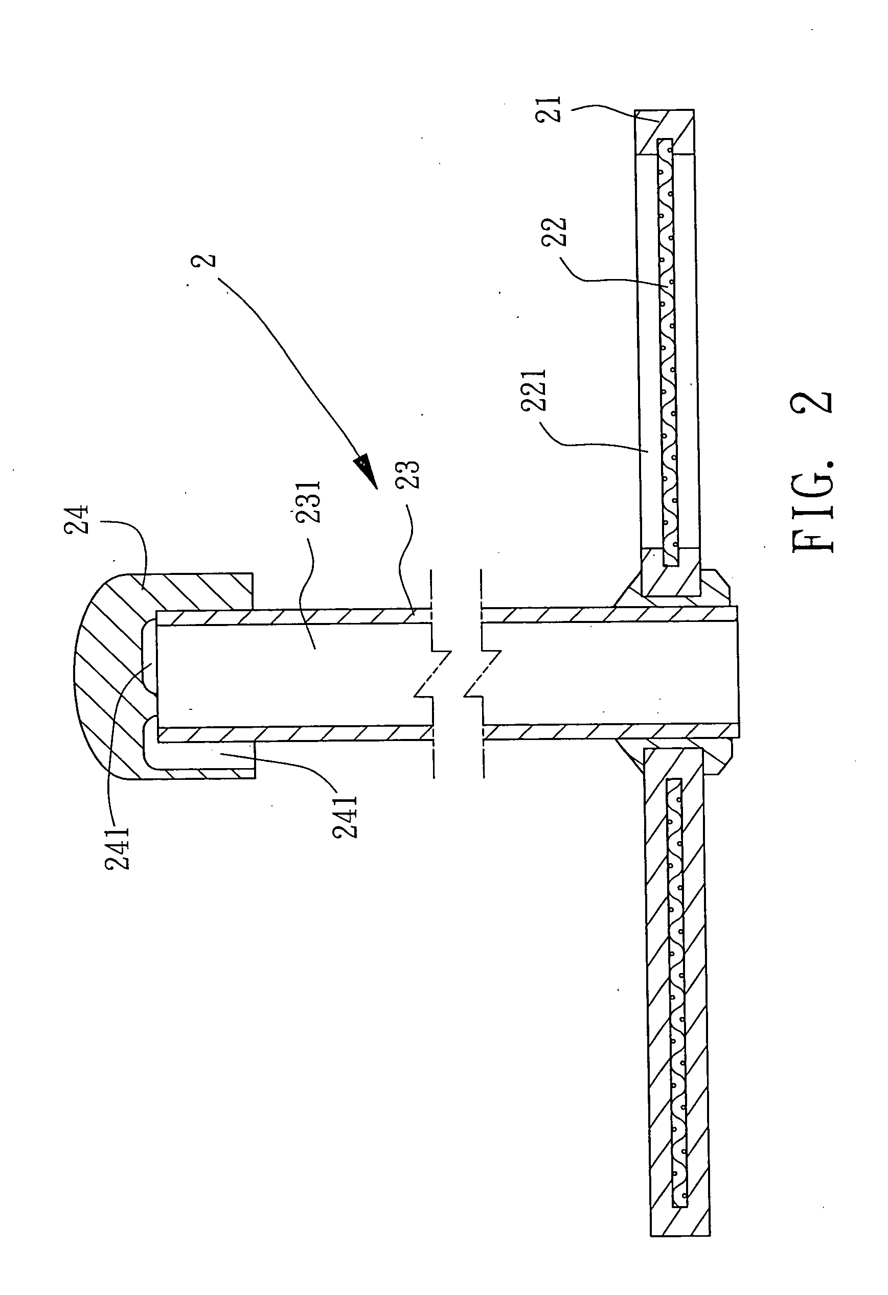
[0023] The filter 2 includes a plane filter mesh 22 and a ventilating tube 23 extending from one face of the filter mesh 22 toward the ...


PUM

PropertyMeasurementUnit
circumferenceaaaaaaaaaa
pressureaaaaaaaaaa
timeaaaaaaaaaa

Abstract

A filter device used in a paint cup of a spraying gun, including a filter mounted in a paint cup body of the paint cup. The bottom of the paint cup body is tapered into a conic shape for connecting with a connecting tube for connecting with the spraying gun. An adjoining section between inner face of the conic bottom of the paint cup body and inner face of a wall of the paint cup body is formed as a fixing section for fixing the filter. The filter includes a plane filter mesh and a ventilating tube extending from one face of the filter mesh toward an opening of the paint cup body. The circumference of the filter mesh is engaged with the fixing section in the paint cup body. The ventilating tube has an internal passage passing through the filter mesh. An upper cap is fitted on one end of the ventilating tube, which end is distal from the filter mesh. The upper cap is formed with at least one ventage communicating with the passage of the ventilating tube and external side.

Description

BACKGROUND OF THE INVENTION [0001] The present invention is related to a filter device used in a paint cup of a spraying gun, and more particularly to a filter device mounted in the paint cup of the spraying gun for filtering off the impurities entrained by the paint. [0002]FIGS. 7 and 8 show the filter device of a conventional spraying gun. The filter device is composed of a cup body 6, a hollow bolt body 61 and a filter 62. The upper and lower ends of outer circumference of the bolt body 61 are formed with outer threads 611. A stop flange 612 is formed in the bottom of the bolt body 61 for stopping the filter 62. The filter 62 is a hollow column covered by a layer of filter mesh 621. Several ribs 622 are formed on outer circumference of the filter mesh 621, whereby a flow way is defined between the bolt body 61 and the filter mesh 621. The paint can flow through the flow way to filter through the filter mesh 621 and then flow into the spraying gun 64. Accordingly, the impurities e...

Claims


Application Information

Patent Timeline
Patent Type & Authority Applications(United States)
IPC IPC(8): B01D35/01B05B7/24
CPCB01D29/055B01D36/001B05B15/008B05B7/2478B05B7/2408B05B15/40
Inventor CHANG, JEN CHIH
Owner CHANG JEN CHIH
Why Eureka
Eureka Blog
Learn More