
Fastening element

a technology of fastening elements and fastening rods, applied in the direction of fastening means, nails, surgery, etc., can solve the problems of increasing friction, and affecting so as to improve the effect of fastening rod rotation, reduce the drive-in energy, and good rotation

Active Publication Date: 2006-02-23
HILTI AG
View PDF23 Cites 10 Cited by
  • Summary
  • Abstract
  • Description
  • Claims
  • Application Information

AI Technical Summary

Benefits of technology

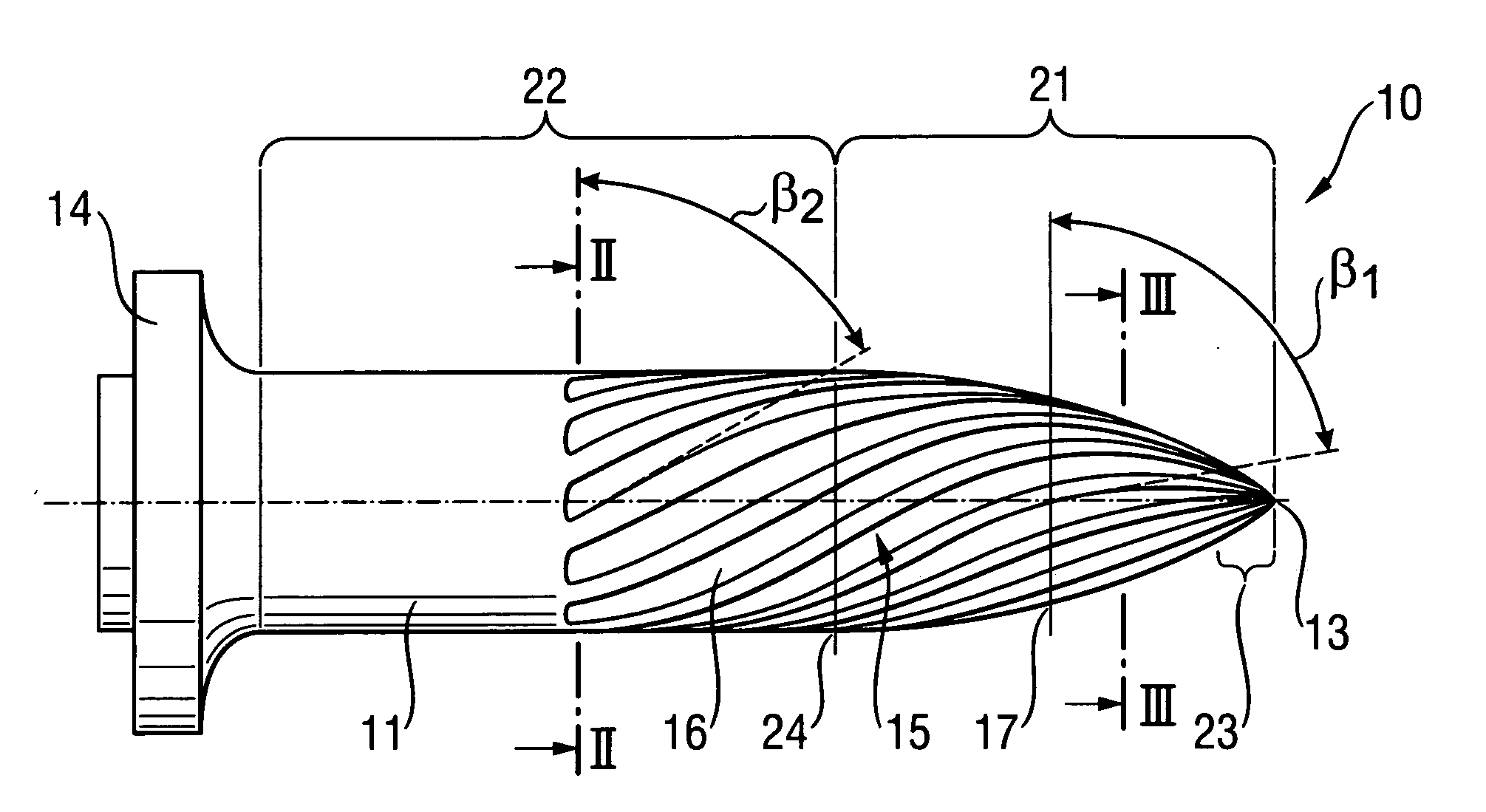
[0011] With the inventive profile geometry, it is insured that the fastening element according to the present invention is drilled in in a constructional component even at high drive-in speeds of more than 50 m / sec, which are attained when the fastening element is driven-in with a combustion-driven setting tool. The rotation of the driven-in fastening element prevents high abrasion of a material of the constructional component. Rather, a thread profile is formed in the constructional component that increases the holding effect of the fastening element in the constructional component because of an improved form locking connection of the fastening element with the constructional component. In metallic constructional components, e.g., an inventive fastening element, which has a stem diameter of 4 mm, permits to obtain a holding value of 15 KN, with a middle drive-in depth of 12 mm.
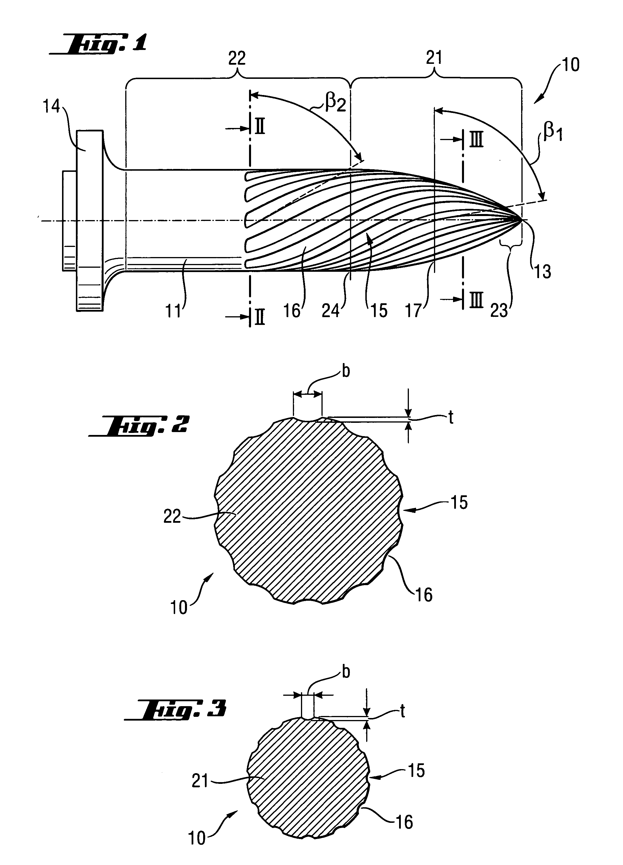
[0014] It is advantageous when the profile depth of the profile grooves in the second section is essentially constant (within manufacturing tolerances) and has a value that lies within a range from 0.04 mm to 0.15 mm. E.g., the profile grooves can have a constant depth of 0.06 mm in the second section. In the first section that adjoins the second section, the depth of the profile grooves decreases toward the tip and lies in a region between 0.01 mm and 0.15 mm E.g., with a constant depth of 0.06 mm of the profile grooves in the second section, the profile depth of the profile grooves in the first section decreases from the depth of 0.06 mm to a minimum of 0.01 mm toward the tip. With these profile depths, a good compromise is achieved that, on one hand, insures a good rotation of the fastening element and, on the other hand, causes only a minimal reduction of the drive-in energy.

Problems solved by technology

This profile increases friction and, therefore, abrasion of the material.
The drawbacks of such fastening element consists in that with thread grooves having the same depth and with an intermediate gradient, at a very rapid drive-in displacement, which is carried out, e.g., with a combustion-driven setting tool, the thread does not lead to rotation of the nail but rather acts as a grater, causing substantial abrasion.

Method used


Image

  • Fastening element
  • Fastening element

Examples


Embodiment Construction

[0021] A fastening element 10 according to the present invention, which is shown in FIGS. 1-3, is formed as a nail having a head 14, a stem 11 adjoining the head 14, and a tip 13 provided at the end of the stem 11 opposite the head 14. The stem has two sections, a first spherical section 21 that directly adjoins the tip 13, and a second, substantially cylindrical section 22 that extends from the end 24 of the first section 21, opposite the tip 13, to the head 14. The region of the second section 22, which is adjacent to the first section 21, is provided with a thread profile 15 that also extends over the first section 21. In the embodiment shown in the drawings, the thread profile 15 has twelve profile groove 16. In the region of the second section 22, the thread profile 15 has a constant steep gradient with a lead angle β2 of 60°. The angle is defined from an equation tan β=Ph / πd, where Ph is the thread profile gradient and d is the diameter of the fastening element 10. In the regi...


PUM


Abstract

A fastening element has a head (14), a stem (11) adjoining the head (14) and having a tip at its end remote from the head (14), a first spherical section (21) extending from the tip (13) in the direction of the head (14) and a second section (22) adjoining the first section (21) and extending in the direction of the head (14), and a thread profile (15) provided on the stem (11) and having, on the second section (22), a constant steep gradient with a lead angle (β2) from 50° to 74° and, on the first section (21), a gradient that increases from the lead angle (β2) of the second section (22) toward the tip (13), with a lead angle (β1) at a half of a length between the tip (13) and the end (24) of the first section (21) remote from the tip (13) amounting to at least 75°.

Description

BACKGROUND OF THE INVENTION [0001] 1. Field of the Invention [0002] The present invention relates to a fastening element having a stem with a tip at one of its ends and head arranged at an end of the stem opposite the tip, with the stem having a first spherical section extending from the tip in the direction of the head, and a second section adjoining the first section at an end of the first section remote from the tip and extending in the direction of the head, and a thread profile provided on the stem. [0003] 2. Description of the Prior Art [0004] Fastening elements of the type described above, such as nails, bolts and the like are usually formed of steel and are used, in fastening technology for securing objects to hard materials such as concrete, metal, and stone. The drive-in process of such fastening elements is carried out with high speed, and the fastening elements are driven-in percussively or otherwise, e.g., with combustion-driven tools. [0005] German Publication DE 101 1...

Claims


Application Information

Patent Timeline
Patent Type & Authority Applications(United States)
IPC IPC(8): A61M29/00F16B15/00F16B19/14
CPCF16B19/14F16B15/00
Inventor ORTLER, RENEDIETZE, SVEN
Owner HILTI AG
Learn More