
Variable stiffness screen

a variable stiffness and screen technology, applied in the field of display units, can solve the problems of insuperable obstacles, rather challenging tasks, and inability to operate in a precise, quick and comfortable manner, and achieve the effect of increasing the flow of visual information

Inactive Publication Date: 2006-02-23
NAKSEN ALEX +1
View PDF12 Cites 139 Cited by
  • Summary
  • Abstract
  • Description
  • Claims
  • Application Information

AI Technical Summary

Benefits of technology

[0015] Accordingly, it is an object of this invention to solve the problems created by the miniaturization of wearable electronic devices accompanied by the increasing flow of visual information, while the human abilities to receive this information by eye remain practically unchanged. More specifically, it is an object of the present invention to provide a lightweight screen display with a viewable area that can be adjusted depending on the volume of information and, ultimately, on the user's needs.
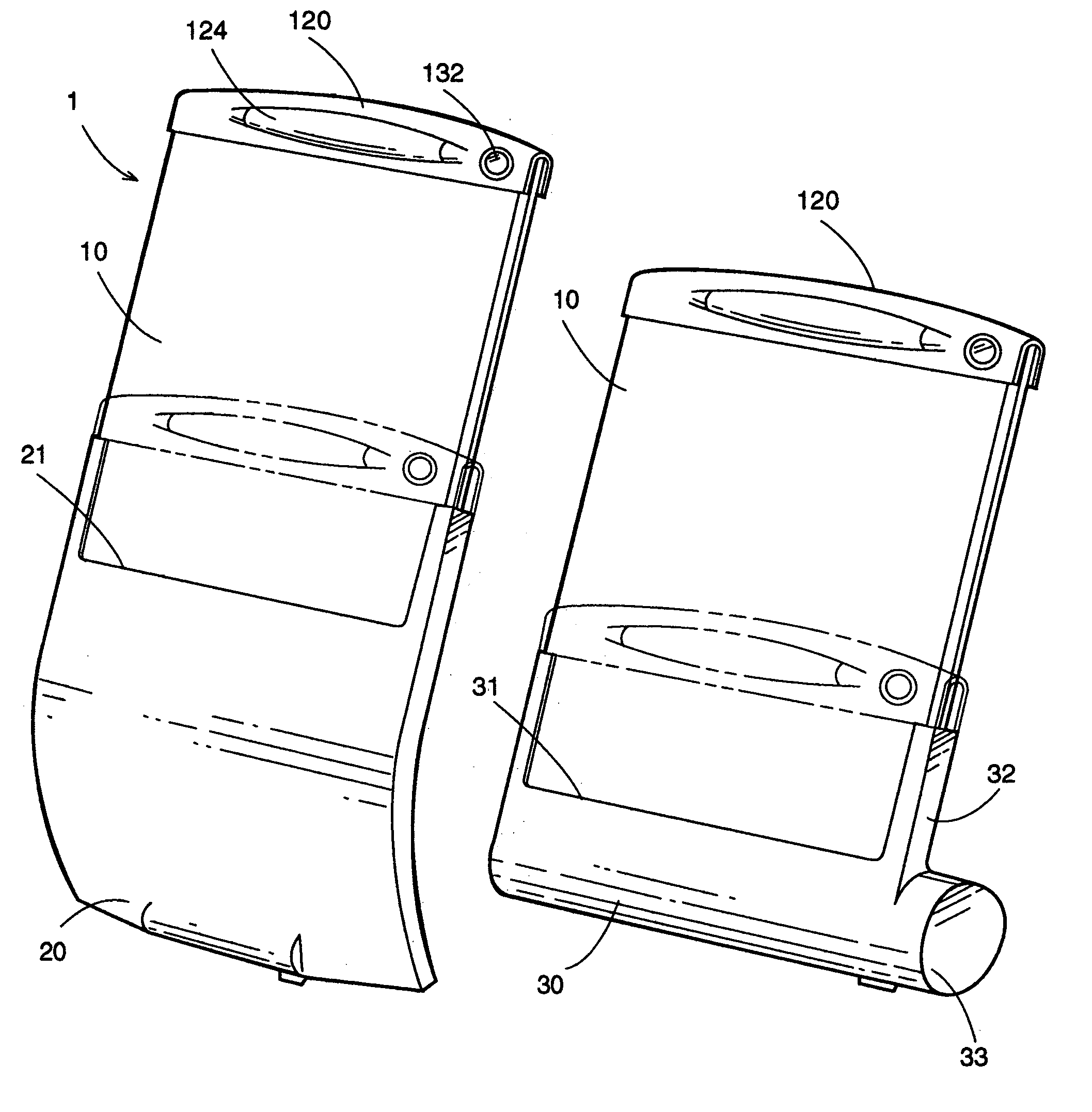
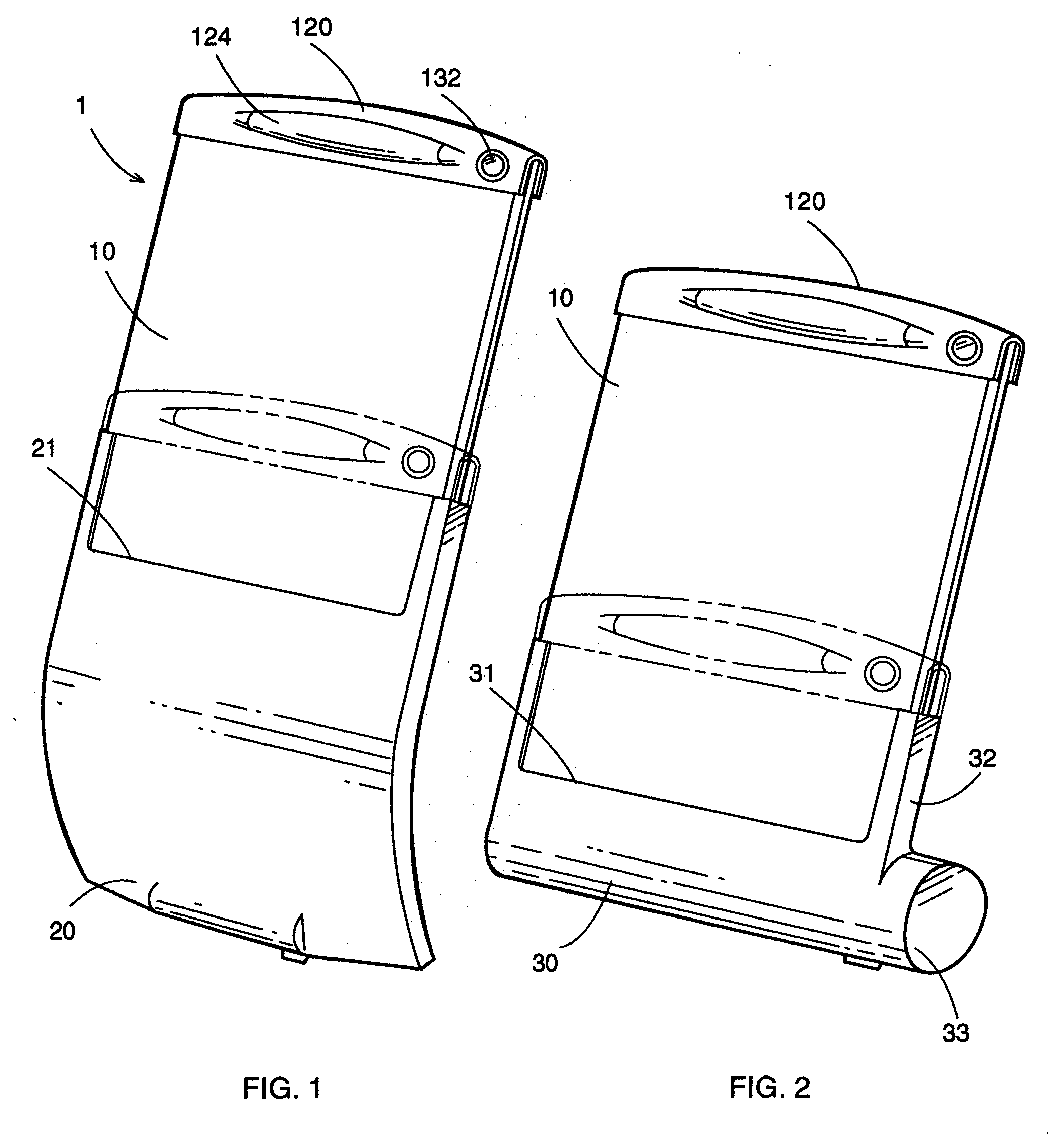
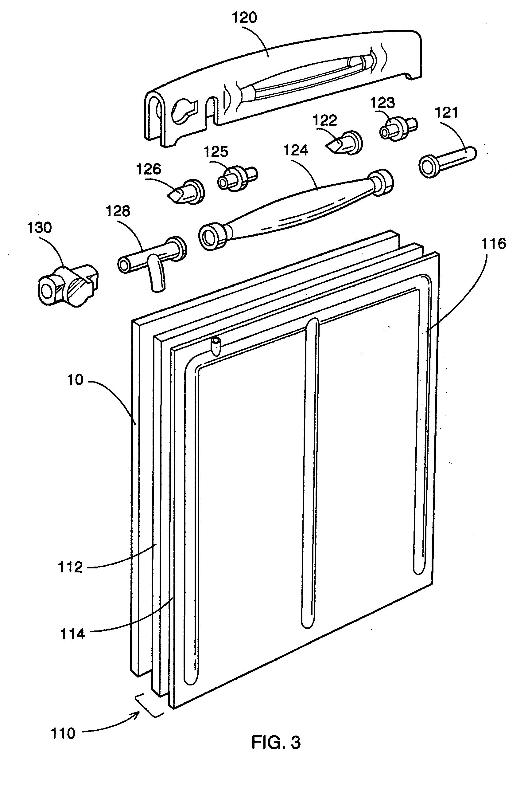
[0016] The variable stiffness screen of this invention makes it possible to change the display size by managing the display's stiffness. In all of the embodiments the variable stiffness screen incorporates a flexible display attached to a certain structural support system. The screen can be encased in a carrying member, either a flexible sleeve or a rigid cartridge. Also the screen can be installed directly into a particular electronic device.
[0017] The main element of the proposed invention is a structural system allowing for changing of the screen's stiffness. The screen's support system in all of its embodiments allows the flexible display to be normally pliable and placed inside the carrying member and, when it is actuated, to be firm and rigid for having a standout working position. The system functions in five preferred embodiments, varying in specific means of supporting the screen.

Problems solved by technology

Being used mostly on the go they have some inherent difficulties not allowing for their operation in a precise, quick and comfortable manner.
Reading anything more than a headline on a screen that is barely larger than an inch square is a rather challenging task for our vision.
On the other hand, the pocket computer / PDAs are equipped with rather readable displays, but their sheer bulk and rigid shape become insuperable obstacles in situations when size and a way of carrying matter.
It may become the main hurdle not allowing the full realization of the immensely potent high-speed “third generation”, or 3G, cellular systems.
In any other position the screen's planar geometry, being supported only partially, would be seriously impaired, making displayed information rather unreadable.
Secondly, it requires a few separate moves for making this system work, including withdrawal of the display, unfolding of the antenna and snapping of the display to it.
Summarizing, the important problems associated with either rollable or foldable electronic screen displays can be identified as follows: a) Miniaturization of wearable electronic devices is limited by the size of an electronic display, which has to be large enough to provide readable visual information.
A technologically achievable much greater volume of visual information is also limited by the display size.
The great potential of 3G cellular systems could not be fully realized, due to the relatively small conventional LCD display.
The apparent limitation of the display size is the device's body itself.
Firstly it has to be rolled or folded for compact storage, thus reducing the overall size of a particular electronic device.
Secondly, it has to be fully opened to display the amount of information associated with either Internet content or a PDA function.
In this position the flexible display is structurally unstable, not allowing for reading of the displayed information in a quick, precise and comfortable manner.
An external support in the form of a rod-like element, an antenna, for instance, limits the user's options of holding the device to only one particular three-dimensional position.
It makes this process unnecessarily cumbersome, especially when one needs to respond to an incoming call.
e) When a foldable screen is supposed to be supported internally, for instance by inflating a structure bonded to the screen, the absence of a built-in actuation means (pumps, valves and so forth) renders the entire system quite inefficient, always dependent on some external help.

Method used


Image

  • Variable stiffness screen
  • Variable stiffness screen
  • Variable stiffness screen

Examples


second alternative embodiment

h Superelastic Support System. FIGS. 28-31

[0104] An alternative embodiment of the variable stiffness screen of the present invention is illustrated in FIG. 28 (front view), FIG. 29 (sectional view), FIG. 30 (enlarged sectional view of a detail), and FIG. 31 (schematic diagram of electrical circuitry). The variable stiffness screen 5 comprises the flexible display 10 attached to a structural support system 500 formed of a temperature activated metal alloy. A handle 520 is mounted at the top of the screen (FIGS. 28 and 29). Similarly to the preferred embodiment, the screen 5 can be encased in a carrying member, either a sleeve 20 or a case 30.

[0105] The superelastic support system is based on the unique ability of shape memory alloys, such as nickel titanium (Nitinol) to return to a predetermined shape when heated. When Nitinol is below its transformation temperature (Martensite crystal structure), it has very low yield strength and can be deformed rather easily. However, when the ma...


PUM


Abstract

A variable stiffness screen for wearable electronic devices provides a viewable area that can be adjusted by managing the screen's physical properties. The screen incorporates a flexible electronic display, attached to a structural system, in which the physical properties can be changed from a flexible state to a rigid one to control the stiffness of the display.

Description

CROSS REFERENCE TO RELATED APPLICATIONS [0001]“Not Applicable”STATEMENT REGARDING FEDERALLY SPONSORED RESEARCH OR DEVELOPMENT [0002]“Not Applicable”REFERENCE TO A SEQUENCE LISTING, A TABLE, OR A COMPUTER PROGRAM LISTING COMPACT DISC APPENDIX BACKGROUND OF THE INVENTION [0003] This invention relates to a display unit and, in particular, to a display unit using a flexible medium, which can be rolled up or folded for compact storage and used in conjunction with electronic communication and processing devices. [0004] Our lives are pervaded by a myriad of various kinds of portable and wearable digital devices, many of which are necessary to operate and used on a daily basis. Being used mostly on the go they have some inherent difficulties not allowing for their operation in a precise, quick and comfortable manner. There is an intrinsic contradiction between the miniaturization of wearable electronic devices accompanied by the increasing flow of visual information and the practically unch...

Claims


Application Information

Patent Timeline
IPC IPC(8): G09G3/00
CPCG06F1/1624G06F1/1637H04M1/0268G06F1/1656G06F1/1652
Inventor NAKSEN, ALEXNAKSEN, DENNIS
Owner NAKSEN ALEX
Learn More