
User identification and password field determination

Inactive Publication Date: 2006-02-16
ROSAR BRUCE
View PDF0 Cites 4 Cited by
  • Summary
  • Abstract
  • Description
  • Claims
  • Application Information

AI Technical Summary

Benefits of technology

[0020] In accordance with another exemplary embodiment, the system of the present invention enables a user to create a logon macro for accessing an application located at a remote computer using a conventional logon procedure without any additional steps required to identify the location of the user ID display field and the password display field. The user ID and password display fields are determined automatically from display fields displayed on a computer monitor with the user simply logging into the application using standard screens displayed on the computer monitor. The present invention enables a user to quickly and easily create a logon macro for accessing a mainframe application without performing cumbersome steps or having to learn new procedures, thereby saving time and effort which can be used to perform other tasks.

Problems solved by technology

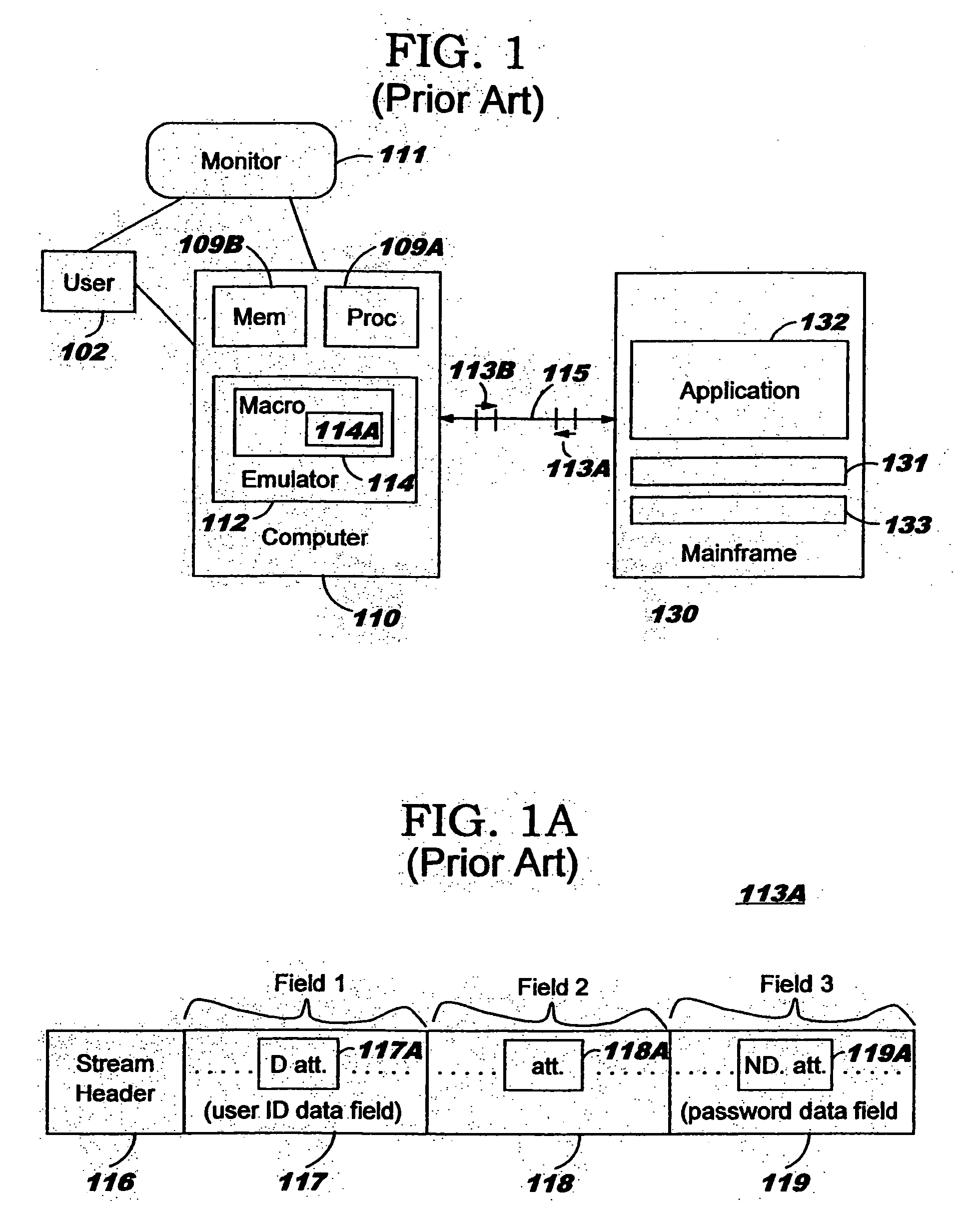
Supplying the user ID and password each time the application 132 is accessed, however, is cumbersome and often unnecessary given modern security techniques such as the secure socket layer (SSL) protocol implemented in many computer systems.
Storing the user ID and password in the logon macro 114A, however, leads to potential security problems.
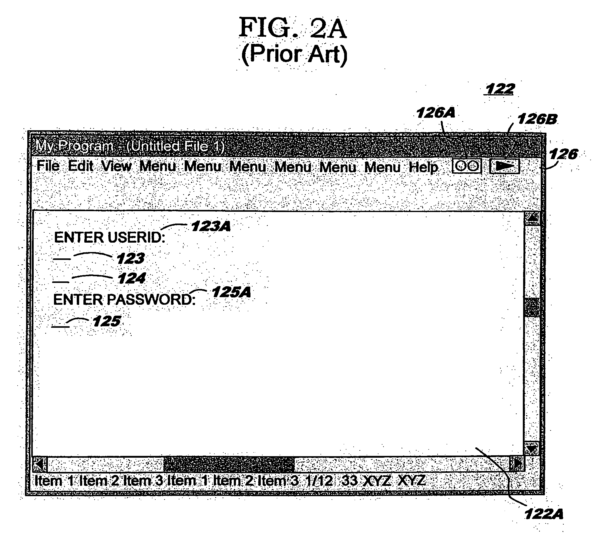
Present systems which attempt to identify the location of the user ID display field 123 and the password display field 125, such as the method used in recently developed emulation systems, are cumbersome for a user to learn and use, and require time and effort for training.

Method used


Image

  • User identification and password field determination
  • User identification and password field determination
  • User identification and password field determination

Examples


Embodiment Construction

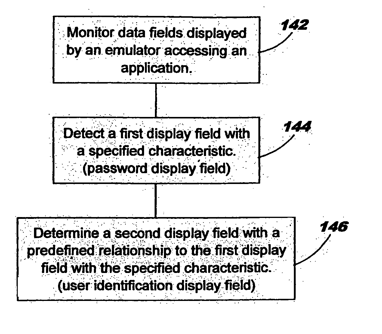
[0028] The present invention relates to a method for automatically identifying display fields displayed on a computer monitor. In accordance with an exemplary embodiment of the present invention, the display field identified are a user identification (user ID) display field and the password display field. Generally, the exemplary embodiment of the present invention comprises identifying the location of the password display field based on a characteristic associated with a display field and then identifying the location of the user ID display field based on a predetermined relationship to the display field identified as the password display field. The user ID and password display fields are determined automatically without requiring a user to manually perform additional steps or supply additional information.

[0029]FIG. 3 depicts a flow chart describing the steps used to identify the user ID display field 123 and the password display field 125 (FIG. 2A) from display fields displayed ...


PUM


Abstract

The present invention is a method for automatically determining a user identification (user ID) display field and a password display field during a logon process. The present invention comprises identifying the password display field based on a characteristic associated with the password display field and then identifying the location of the user ID display field based on a predetermined relationship to the identified password display field.

Description

CROSS REFERENCES TO RELATED APPLICATIONS [0001] The present application is related to and claims priority from U.S. patent application entitled, “User Identification and Password Field Determination”, having application Ser. No. 09 / 777,287, and filed on Feb. 6, 2001, currently pending, which is assigned to the assignee of the present invention. The above identified application is incorporated by reference herein in its entirety.BACKGROUND OF THE INVENTION [0002] The present invention relates to computer systems and, more particularly, to a method for determining the location of a user identification display field and a password display field during a logon process. [0003] In present computer systems it is common for a user working on one computer to access applications residing on another computer, such as a mainframe computer, as depicted in FIG. 1. Emulation software running on a processor 109A of a user's computer 110 enables the computer 110 to communicate with the mainframe com...

Claims


Application Information

Patent Timeline
IPC IPC(8): G06F17/00G06F3/00G06F3/14G06F17/24G06F21/00H04L29/06
CPCG06F17/243H04L63/083G06F21/41G06F40/174
Inventor ROSAR, BRUCE
Owner ROSAR BRUCE
Learn More