
Mounting apparatus for storage device

Inactive Publication Date: 2006-02-16
HONG FU JIN PRECISION IND (SHENZHEN) CO LTD +1
View PDF16 Cites 77 Cited by
  • Summary
  • Abstract
  • Description
  • Claims
  • Application Information

AI Technical Summary

Benefits of technology

[0007] To address the aforementioned problems, a plurality of mounting apparatuses is invented to reduce the number of needed screws. For example, a pair of detachable rails is attached to opposite sides of a storage device with screws. The storage device slides into and is secured to a drive bracket. However, the screws have to be removed to detach the rails from the storage device before replacing the storage device.
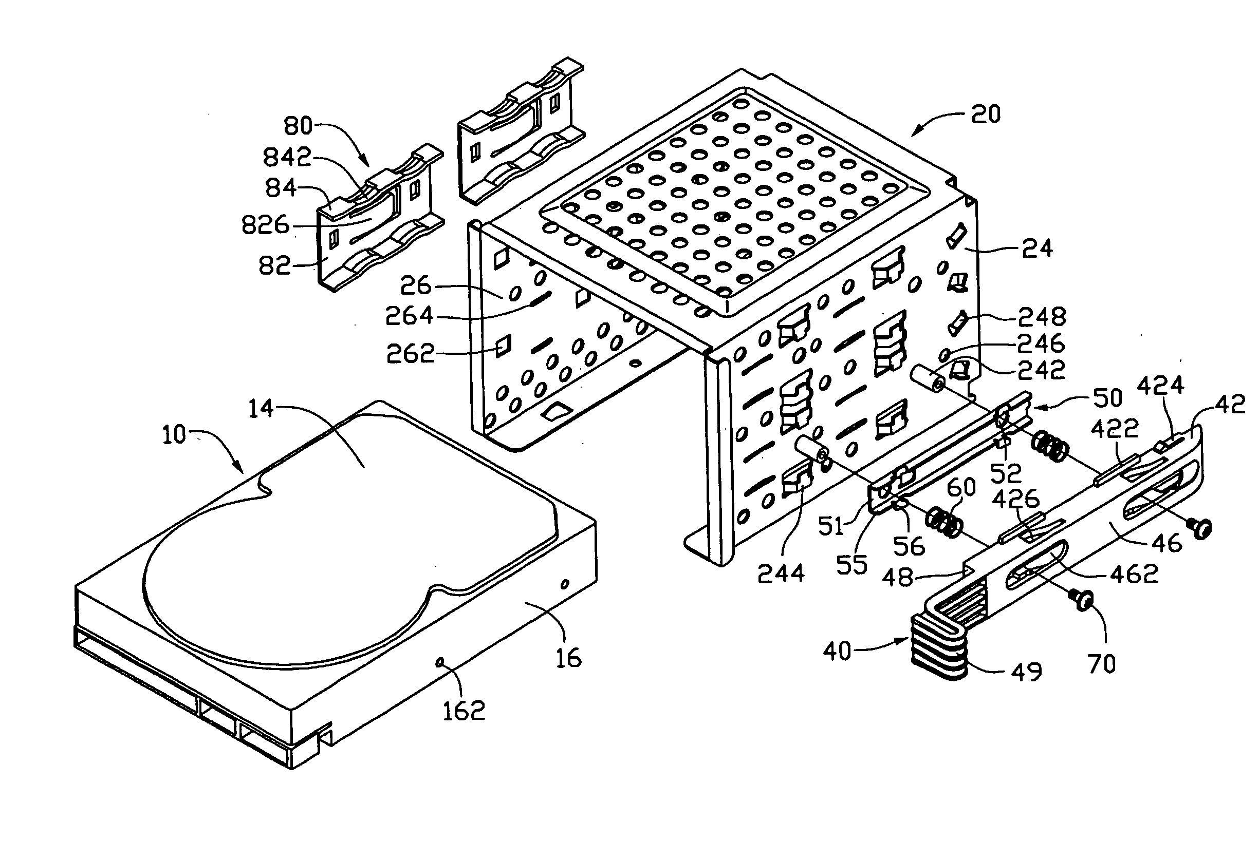
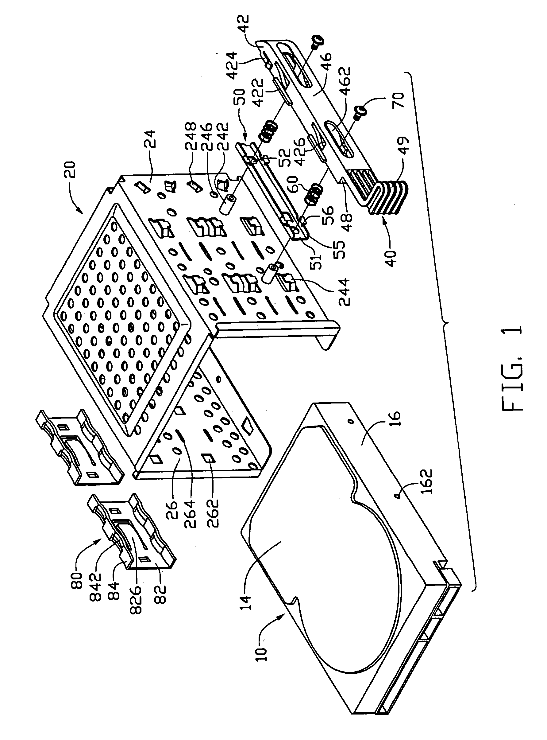
[0013]FIG. 1 is an exploded, isometric view of a mounting apparatus and a storage device in accordance with a preferred embodiment of the present invention;
[0015]FIG. 3 is an assembled view of the mounting apparatus of FIG. 1; and
[0016]FIG. 4 is an assembled view of FIG. 1, showing the storage device is held in place.

Problems solved by technology

However, the installation of such devices in the electronic apparatus is always labor-intensive.
Usually, these screws are small enough making them difficult to manipulate and install.
It is laborious and time-consuming to manually manipulate the screws.
Some accidental damage will occur in the computer due to impact of these moving parts, and the like causes.
However, the screws have to be removed to detach the rails from the storage device before replacing the storage device.
However, the storage device is apt to be unwillingly detached from the bracket due to inadvertently depressing the extension strips.
As manufacturers focus on designing mounting apparatus that facilitates installing a storage device, shock problem that the storage device may encounter when the electronic apparatus falls over is improperly neglected.

Method used


Image

  • Mounting apparatus for storage device
  • Mounting apparatus for storage device
  • Mounting apparatus for storage device

Examples


Embodiment Construction

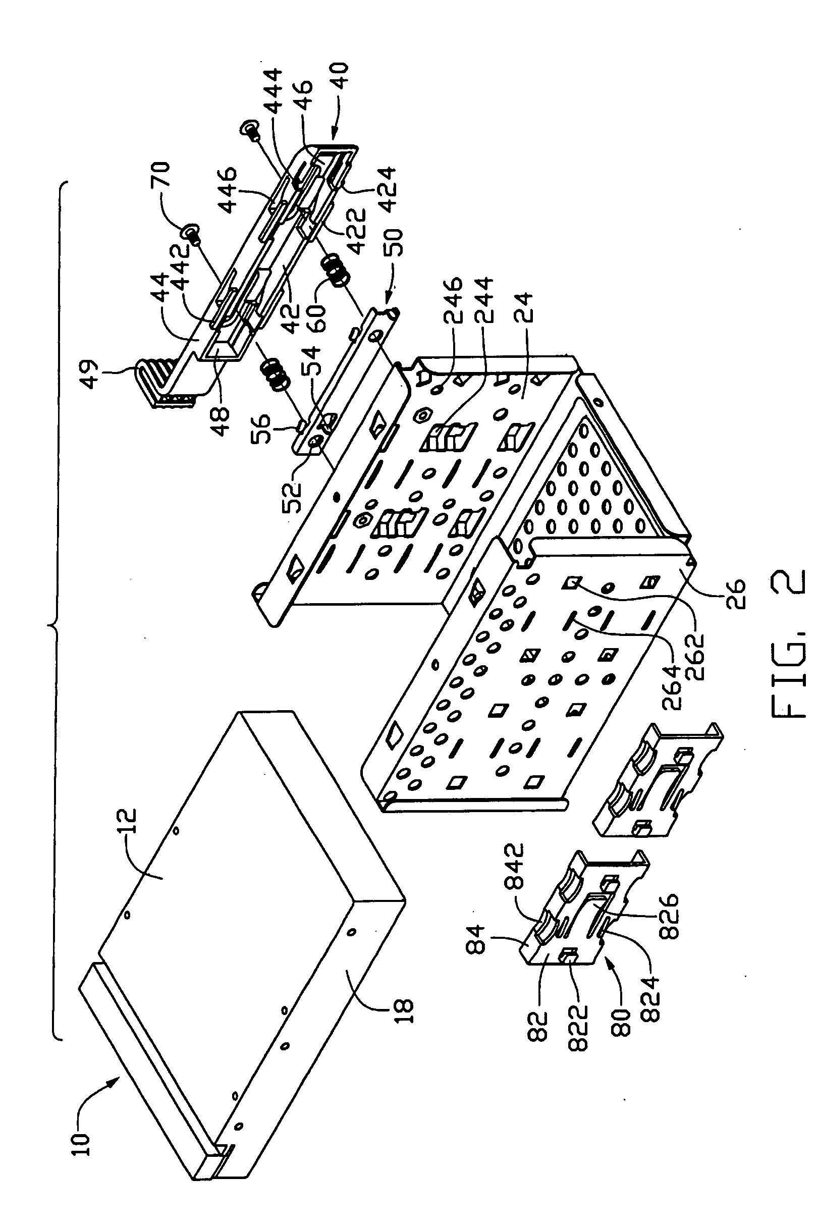
[0017] Referring to FIGS. 1 and 2, in a preferred embodiment of the invention, a mounting apparatus of an electronic device like a computer is provided for holding a functional device like a storage device 10 of the computer in place. The mounting apparatus includes a bracket 20, a slidable member 40, a retention member 50, and a pair of shock absorbers 80.

[0018] The storage device 10 includes a top wall 14, a bottom wall 12, and a pair of sidewalls 16, 18, and two holes 162 are defined in the side wall 16.

[0019] The bracket 20 includes a pair of opposite first and second sidewalls 24, 26. Two horizontally spaced projections 242 are formed on an outer surface of the first sidewall 24, each projection 242 defining an internal threaded hole. A pair of retaining pieces 244 is punched outwardly from the first sidewall 24 and is generally located below the projections 242. Another pair of retaining pieces 244 is located at the top of the projections 242. A pair of through holes 246 is ...


PUM


Abstract

A mounting apparatus includes a bracket (20), a slidable member (40), a retention member (50), and a pair of shock absorbers (80). The bracket is for receiving a storage device (10) therein, the bracket including a pair of opposite first and second sidewalls (24, 26), and a pair of through holes (246) is defined in the first sidewall. The slidable member is movably attached to the first sidewall of the bracket. The retention member is spring-loaded, and is movable relative to the slidable member and the first sidewall respectively in different directions. A pair of latches (54) is formed on the retention member, the latches being capable of being extended through the through holes respectively for engaging the storage device. The shock absorber is arranged to an internal surface of the second sidewall for engaging the storage device.

Description

CROSS-REFERENCE TO RELATED APPLICATIONS [0001] Relevant subject matter is disclosed in a co-pending U.S. Patent Application entitled “MOUNTING APPARATUS FOR STORAGE DEVICES”, assigned to the same assignee of this application with an application Ser. No. 10 / 951,425.BACKGROUND OF THE INVENTION [0002] 1. Field of the Invention [0003] The present invention relates to a mounting apparatus, and more particularly to a mounting apparatus for a storage device. [0004] 2. General Background [0005] The manufacture and assembly of electronic apparatuses has become increasingly more competitive. Manufacturers continually strive to improve the design and features of electronic apparatuses yet still offer competitive prices. One such area of improvement is mounting of devices in an electronic apparatus. An electronics apparatus, such as a typical desktop computer, tower, server, and the like, usually include storage devices, such as hard disk drives, compact disk read-only memory (CD-ROM) drives, d...

Claims


Application Information

Patent Timeline
IPC IPC(8): G06F1/16G06F1/18G11B33/08G11B33/12
CPCG06F1/184G11B33/128G06F1/187
Inventor XU, JI-GUO
Owner HONG FU JIN PRECISION IND (SHENZHEN) CO LTD
Learn More