Novel bits and cutting structures

a cutting structure and new technology, applied in drill bits, earthwork drilling and mining, construction, etc., can solve the problems of shortening the life of both natural and synthetic diamonds, affecting the cutting effect of pdc bit bodies, and difficult materials used in forming pdc bit bodies

Inactive Publication Date: 2006-02-16
SMITH INT INC
View PDF32 Cites 232 Cited by
  • Summary
  • Abstract
  • Description
  • Claims
  • Application Information

AI Technical Summary

Problems solved by technology

It has been found, however, that the life of both natural and synthetic diamond is shortened by the lifetime thermal exposure experienced in the furnace during the infiltration process.
The materials used to form PDC bit bodies, in order to be resistant to wear, are very hard and difficult to machine.
Although PDC cutting elements offer the benefit of being able to tailor a particular cutting element to a particular formation, they are also subject to thermal degradation at the high temperatures often encountered within the wellbore during the drilling process.
), the metallic binder expands much more rapidly than the diamond, resulting in fracturing of the diamond table and degradation of the PDC cutting element.
These sharp edges 402, 404 that contact the support have been shown to create stress risers within the support, leading to cracking of the support and delamination of the TSP cutting element.
However, many formations have mixed characteristics (i.e., the formation may include both hard and soft zones), which may reduce the rate of penetration of a bit (or, alternatively, reduces the life of a selected bit) because the selected bit is not preferred for certain zones.
In this type of formation, if a conventional diamond-impregnated bit is used, because the diamond table exposure of this type of this bit is small, the shale can fill the gap between the exposed diamonds and the surrounding matrix, reducing the cutting effectiveness of the bit (i.e., decreasing the rate of penetration (ROP)).
In contrast, if a PDC cutter is used, the PDC cutter will shear the shale, but the abrasive sand will cause rapid cutter failure (i.e., the ROP will be sufficient, but wear characteristics will be poor).
Moreover, increasing the diameter of the wellbore may be necessary if, for example, the formation being drilled is unstable such that the wellbore diameter decreases after being drilled by the drill bit.
Moreover, it is difficult to directionally drill a wellbore with a large diameter bit because, for example, larger diameter bits have an increased tendency to “torque-up” (or stick) in the wellbore.

Method used


Image

  • Novel bits and cutting structures
  • Novel bits and cutting structures
  • Novel bits and cutting structures

Examples


Embodiment Construction

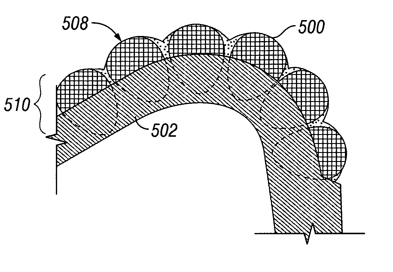
[0065] One aspect of the present invention relates to a cutting structure that uses a shearing element, disposed on a support. In particular, the present invention relates to a cutting structure for use in lieu of, or in combination with, PDC cutter elements to provide a shearing action. Embodiments of the present invention are particularly useful in high speed applications, such as applications that use a mud motor and / or turbines.

[0066] In another embodiment of the present invention, at least a portion of the shearing element is overlaid by a retaining element to provide an additional retention mechanism to prevent the shearing element from dislodging from the support. The retaining element may be integrally formed with the support, or may be discretely applied to the shearing element and formed from either the same composition as the support or a different composition.

[0067] In another embodiment of the present invention, diamond impregnated blades, which are used in lieu of th...


PUM


Abstract

This invention provides an improved cutting element for downhole cutting tools including a support element and a beveled shearing element disposed on the support element and a drill bit including the cutting element; a cutting element including a support element and a shearing element disposed on the support element, wherein the shearing element includes TSP, a sharpened cutting edge, and at least one blended edge that forms part of an interface with the support element and a drill bit including the cutting element. Cutting inserts including an insert body and the shearing elements disclosed above are provided. Also provided are methods for forming the cutting elements and drill bit inserts and a method for drilling mixed earth formations using the improved downhole cutting tools of the present invention.

Description

CROSS-REFERENCE TO RELATED APPLICATIONS [0001] This application is a continuation-in-part of U.S. patent application Ser. No. 11 / 154,284 filed on Jun. 16, 2005, which is a continuation-in-part of U.S. patent application Ser. No. 10 / 696,535, filed on Oct. 29, 2003, which claims priority of U.S. Provisional Application Ser. No. 60 / 446,967, filed on Feb. 12, 2003, and U.S. patent application Ser. No. 10 / 967,584, filed on Oct. 18, 2004, which is a continuation of U.S. patent application Ser. No. 10 / 738,629. All these parent applications are hereby incorporated by reference in their entirety.BACKGROUND OF INVENTION [0002] 1. Field of the Invention [0003] The present invention relates generally to downhole cutting tools used in the oil and gas industry. More specifically, the present invention relates to improved cutting structures. [0004] 2. Background Art [0005] Rotary drill bits with no independently moving elements on them are typically referred to as “drag” bits in the art. Drag bits...

Claims


Application Information

Patent Timeline
Patent Type & Authority Applications(United States)
IPC IPC(8): E21B10/36
CPCE21B10/5673E21B10/55
Inventor AZAR, MICHAEL GEORGETHIELE, JONATHAN CRAIGRAY, TOMMY GENECHUNN, GARYALSUP, SHELTON W.
Owner SMITH INT INC
Why Eureka
Try Eureka