
All-pass network for data transmission over a CATV system

a catv system and network technology, applied in the field of wired network for data transmission, can solve the problem of high incidence of bit errors in the return path

Inactive Publication Date: 2006-02-09
PPC BROADBAND INC
View PDF8 Cites 11 Cited by
  • Summary
  • Abstract
  • Description
  • Claims
  • Application Information

AI Technical Summary

Benefits of technology

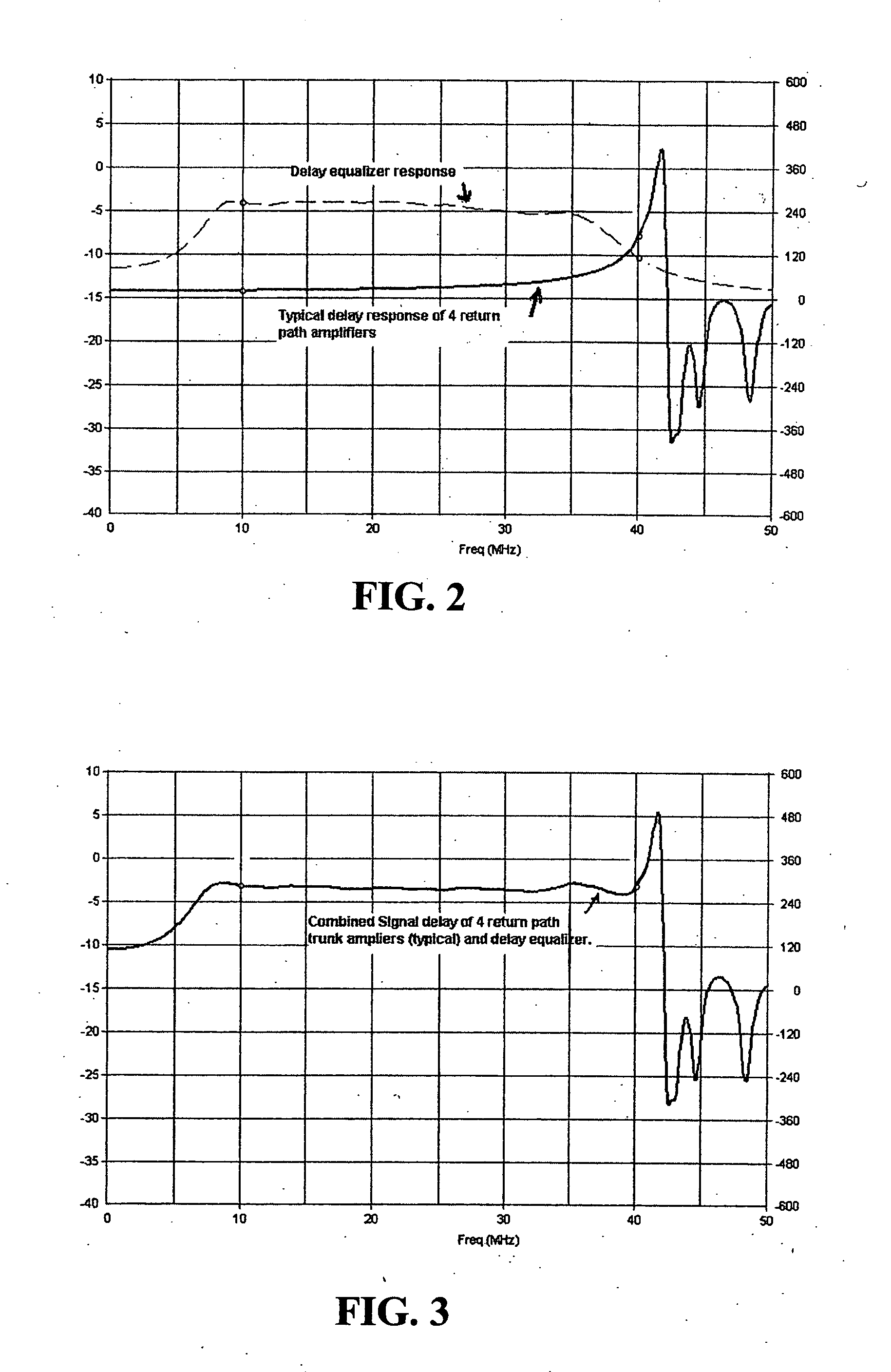
[0005] The present invention addresses the above needs and achieves other advantages, by providing a cable system, and a method for configuring a path of a cable system, wherein the group delay caused by one or more diplex filter networks in a path of the system is substantially equalized over all frequencies within a predetermined band by the use of one or more all-pass delay equalizers in the path. A method of configuring a path in accordance with one embodiment of the invention includes steps of determining a collective delay versus frequency characteristic of the path within the predetermined frequency band caused by the diplex filter network(s), and providing from one to a plurality of all-pass delay equalizers in the path, wherein a collective delay versus frequency characteristic of the all-pass delay equalizer(s) within a predetermined frequency band is substantially a mirror image of that caused by the diplex filter network(s), such that all frequencies within the predetermined frequency band are delayed by substantially the same amount and hence all frequency components of a signal occupying the predetermined frequency band arrive at a receiver in the path at substantially the same time.

Problems solved by technology

One factor that can lead to higher incidence of bit errors in the return path (i.e., the path from the end user to the head end facility) of a cable system is so-called group delay, wherein one or more frequency components of the return signal arrive at the head end facility at a slightly different time than one or more other frequency components that were transmitted by the end user at the same time.

Method used


Image

  • All-pass network for data transmission over a CATV system
  • All-pass network for data transmission over a CATV system
  • All-pass network for data transmission over a CATV system

Examples


Embodiment Construction

[0017] The present inventions now will be described more fully hereinafter with reference to the accompanying drawings, in which some but not all embodiments of the invention are shown. Indeed, these inventions may be embodied in many different forms and should not be construed as limited to the embodiments set forth herein; rather, these embodiments are provided so that this disclosure will satisfy applicable legal requirements. Like numbers refer to like elements throughout.

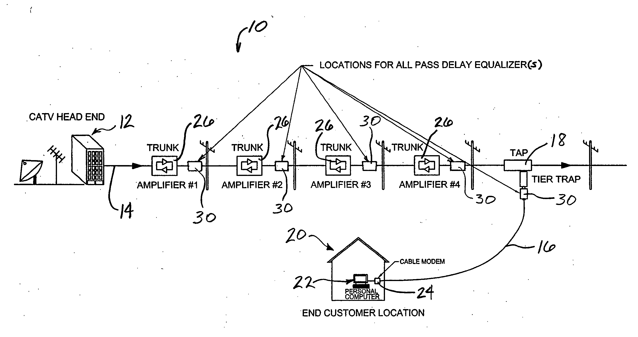
[0018]FIG. 1 schematically shows a portion of a cable system 10 in accordance with one embodiment of the invention. The system includes a head end facility 12 from which emanate a plurality of main distribution lines or trunks 14 (only one shown for simplicity of illustration) in a hub-and-spoke type configuration. Typically a plurality of feeder lines 16 branch off the trunk 14 at one or more taps 18 (only one tap and feeder line shown for simplicity) for servicing a relatively small number of end users 20 in...


PUM


Abstract

A cable system, and a method for configuring a path of a cable system, wherein the group delay caused by one or more amplifiers having diplex filter networks is substantially equalized over all frequencies within a predetermined band by the use of one or more all-pass delay equalizers. A method of configuring a path includes steps of determining a delay versus frequency characteristic of the path within the predetermined frequency band, and providing from one to a plurality of all-pass delay equalizers in the path, wherein a collective delay versus frequency characteristic of the all-pass delay equalizer(s) within a predetermined frequency band is a mirror image of that caused by the amplifier(s), such that all frequencies within the predetermined frequency band are delayed by substantially the same amount and hence all frequency components of a signal arrive at a receiver at substantially the same time.

Description

BACKGROUND OF THE INVENTION [0001] This invention relates to wired networks for transmission of data, and particularly relates to cable television (CATV) networks for data transmission. [0002] Cable television (CATV) systems generally comprise a head end facility from which a plurality of trunks or main distribution lines emanate in a hub-and-spoke arrangement. Each trunk serves one or more local distribution networks each of which serves a relatively small number (e.g., about 100 to 250) of end users. Each end user is connected with one of the trunks via a feeder line that taps into the main trunk at a feeder tap location. [0003] As CATV services have expanded from simple unidirectional services in which signals are sent only from the service provider to the end user, but not vice versa, to bidirectional services in which signals are also sent from the end users back to the service provider, the demands for high performance of the cable system have also expanded. In particular, whe...

Claims


Application Information

Patent Timeline
Patent Type & Authority Applications(United States)
IPC IPC(8): H04N7/173
CPCH04N7/17309H04N7/102H04N21/6118
Inventor SHAFER, STEVEN K.PALINKAS, RAYMONDOLCEN, AHMET BURAK
Owner PPC BROADBAND INC
Learn More