
Serial ATA cable assembly with small size

Inactive Publication Date: 2006-02-09
HON HAI PRECISION IND CO LTD
View PDF8 Cites 8 Cited by
  • Summary
  • Abstract
  • Description
  • Claims
  • Application Information

AI Technical Summary

Benefits of technology

[0007] A main object of the present invention is to provide a cable assembly having a small size and a simple structure.

Problems solved by technology

Today, not only are processor speeds increasing, but the amount of space that a computer fits into is shrinking.
Therefore, the motherboards or printed circuit boards (PCBs) that hold the electronics and other devices for a computer have limited space.
This takes up considerable space, depending on the number of hard disk drives and associated Serial ATA connectors.
However, the passageways are only defined in a longitudinal wall of the insulative housing, and the plurality of standard Serial ATA cables and single wires are arranged in a side-by-side so that the Serial ATA cable assembly has a relatively long length in a longitudinal direction, thus the cable assembly will still occupy larger valuable space in the motherboard.

Method used


Image

  • Serial ATA cable assembly with small size
  • Serial ATA cable assembly with small size
  • Serial ATA cable assembly with small size

Examples


first embodiment

[0028]FIG. 6 illustrates a cable assembly system 100 having a pair of cable assemblies 1000 according to the present invention in two ends of a set of cables.

second embodiment

[0029]FIGS. 7 and 8 illustrate a cable assembly system 200 having a cable assembly 1000 according to the present invention in only one end of a set of cables and a plurality of single position seven pin connectors 2000 in the other end of the set of cables. The connector 2000 is detailedly disclosed in U.S. patent application Ser. No. 10 / 776,111 filed on Feb. 10, 2004 and entitled “CABLE END CONNECTOR ASSEMBLY HAVING LOCKING MEMBER”, which is invented by the same inventor and assigned to the same assignee as this application. The disclosure of the related patent application is wholly incorporated herein by reference. Thus, the connector 2000 is given unnecessary details herein.

[0030] It is to be understood, however, that even though numerous characteristics and advantages of the present invention have been set forth in the foregoing description, together with details of the structure and function of the invention, the disclosure is illustrative only, and changes may be made in detai...


PUM


Abstract

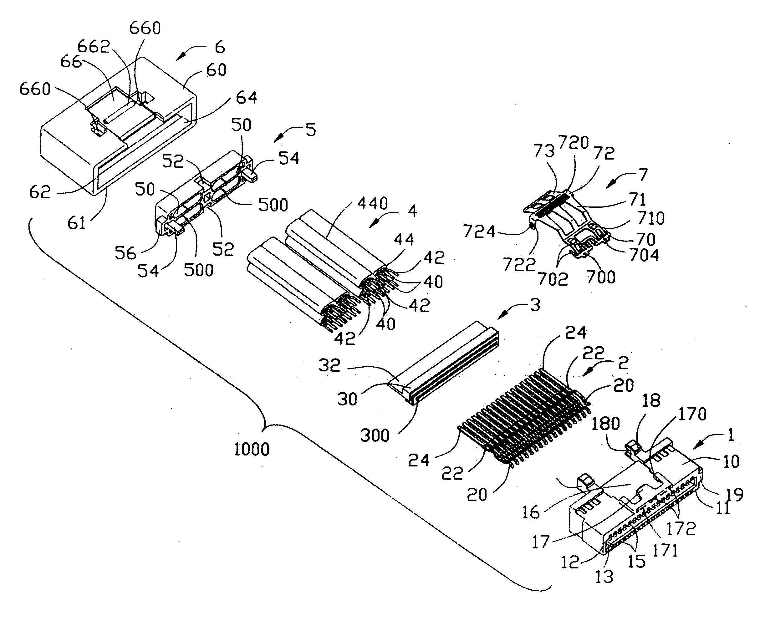
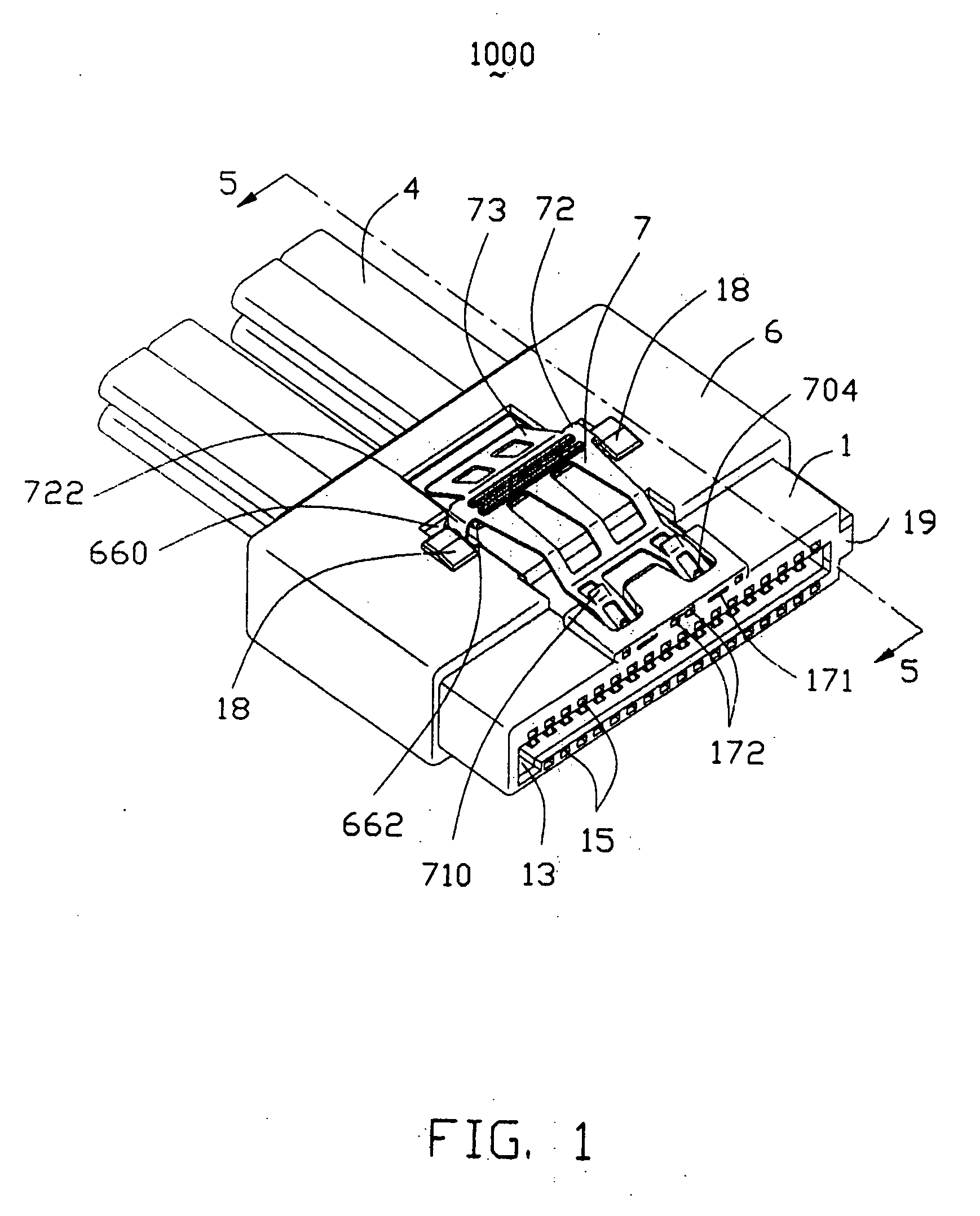
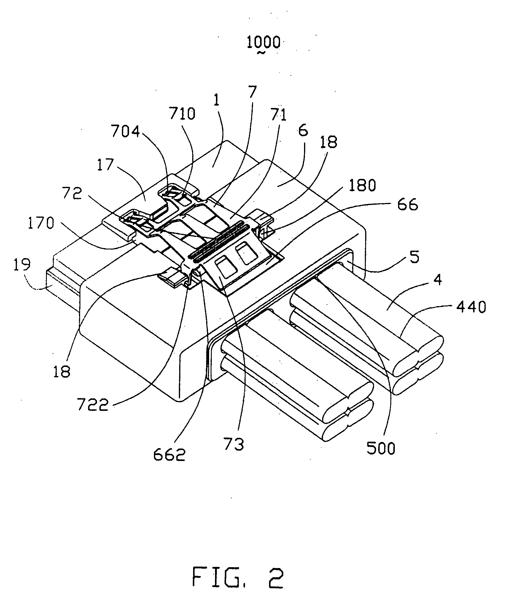
A Serial ATA cable assembly (1000) having a small size includes an housing (1), upper and lower rows of contacts (2), a contact spacer (3), a number of standard Serial ATA cables (4) arranged in two rows, a cable spacer (5) defining two rows of receiving cavities for receiving corresponding cables, a cover (6) over-molding a rear portion of the housing, a front portion of the cables and the cable spacer, and a locking member (7) assembled onto the housing and the cover. The housing includes an upper wall (10), an opposite bottom wall (11) and a pair of sidewalls (12) connecting with the upper and the bottom walls. The walls together define an L-shaped receiving space (13). The upper and the bottom walls each defines a row of passageways for receiving the upper and the lower rows of contacts.

Description

BACKGROUND OF THE INVENTION [0001] 1. Field of the Invention [0002] The present invention generally relates to a cable assembly, and more particularly to a Serial ATA cable assembly with small size. [0003] 2. Description of Related Art [0004] Currently, Serial Advanced Technology Attachment (Serial ATA) connectors are only single position seven pin connectors. Today, not only are processor speeds increasing, but the amount of space that a computer fits into is shrinking. Therefore, the motherboards or printed circuit boards (PCBs) that hold the electronics and other devices for a computer have limited space. In a computer which may contain multiple hard drives, multiple Serial ATA connectors and Serial ATA cable assemblies may need to reside on the printed circuit board and occupy the space of the computer. This takes up considerable space, depending on the number of hard disk drives and associated Serial ATA connectors. [0005] Therefore, there is a need for integrating overall Seri...

Claims


Application Information

Patent Timeline
IPC IPC(8): H01R9/03
CPCH01R13/6275H01R31/005H01R24/60H01R2107/00H01R43/24
Inventor WU, JERRY
Owner HON HAI PRECISION IND CO LTD
Learn More