
Monitoring apparatus and method of displaying bird's-eye view image

a technology of monitoring apparatus and image, which is applied in the field of monitoring apparatus and method of displaying birdseye view image, can solve the problems of complicated image processing, increased work and time, and increased processing time, and achieves the effect of safe driving

Active Publication Date: 2006-02-09
KK TOSHIBA
View PDF3 Cites 47 Cited by
  • Summary
  • Abstract
  • Description
  • Claims
  • Application Information

AI Technical Summary

Benefits of technology

[0014] The present invention has been made in view of the circumstances described above. It is an object of the present invention to provide a monitoring apparatus and a method of displaying bird's-eye view images, which picks up images around a vehicle, etc., with a few fish-eye cameras to obtain a wide-angle image, and which can convert the fish-eye images into bird's-eye view images at a high speed.
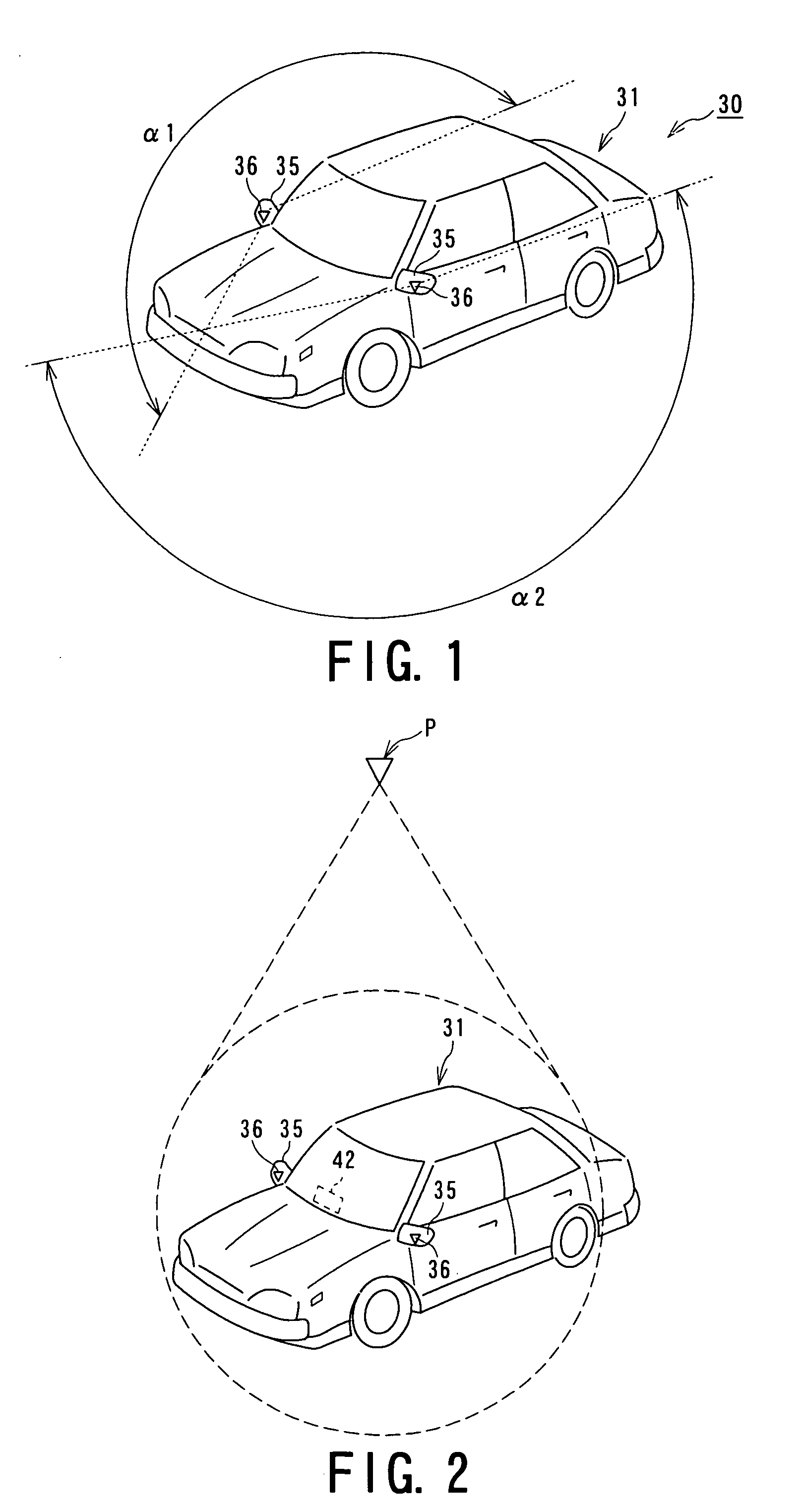
[0019] According to the present invention, it is possible to create a bird's-eye view by setting a hypothetical view point above a vehicle, etc., based on the images picked up including blind-spot areas around a vehicle, etc., using fish-eye cameras installed at predetermined positions of a moving body such as a vehicle, etc.
[0020] Accordingly, it has become possible to see the bird's-eye view images around the vehicle at the driver's side, and thus the driver can easily check the location of an obstacle, etc., around the vehicle. It is therefore possible to provide a monitoring apparatus and a method of displaying bird's-eye view images which can contribute to safe driving by preventing the vehicle from hitting or bumping a body such as this obstacle, etc.

Problems solved by technology

In this case, it is necessary to perform the composite processing of many images, and thus the image processing becomes complicated and it becomes necessary to take much processing time.
Further, the mapping table must be created in advance, and thus it is necessary to take much work and time for creating that table.

Method used


Image

  • Monitoring apparatus and method of displaying bird's-eye view image
  • Monitoring apparatus and method of displaying bird's-eye view image
  • Monitoring apparatus and method of displaying bird's-eye view image

Examples


second embodiment

of the Online-image Creation Unit

[0095] The monitoring apparatus 30 of the present invention may adopt GPU (graphics processor unit) so as to generate an online image. Since GPU has a dewarping image processing function for performing the dewarping image processing, and a bird's-eye view image processing function for performing bird's-eye view image processing (GPU function), GPU is capable of performing the dewarping image processing and the bird's-eye view image processing at a high speed.

[0096] According to the monitoring apparatus 30 adopted GPU 82, in the view of the fact that the left-hand side of the first expression in Expression 2 is an expression by homogeneous coordinates, the calculation of the texture in Expression 2 can be executed, for example, by calculating four corner points of the bird's-eye view image to be displayed by Expression 2 in advance, and then by performing texture mapping the inside of the figure in the homogeneous coordinate mode.

[0097] The monitori...


PUM


Abstract

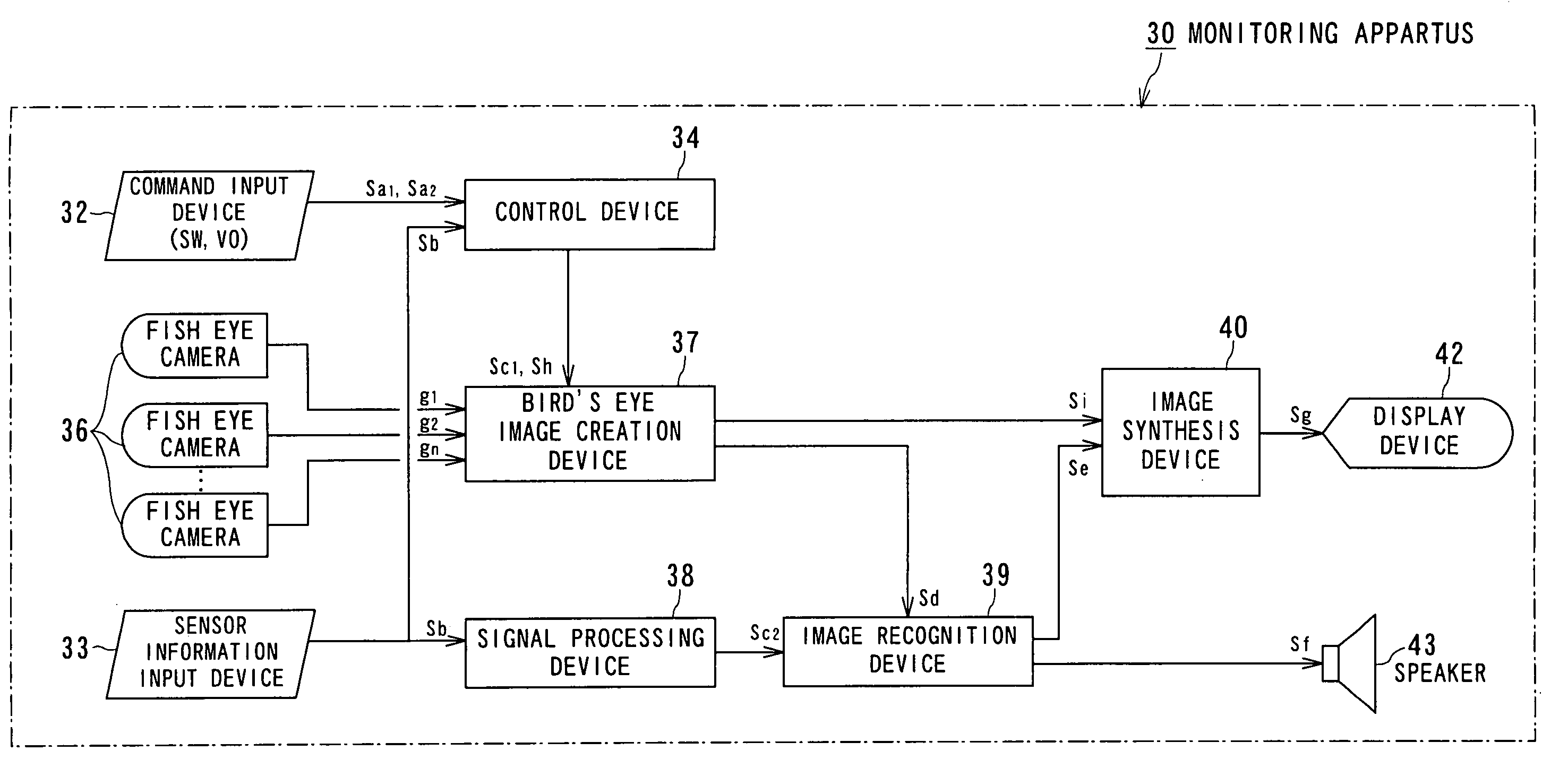
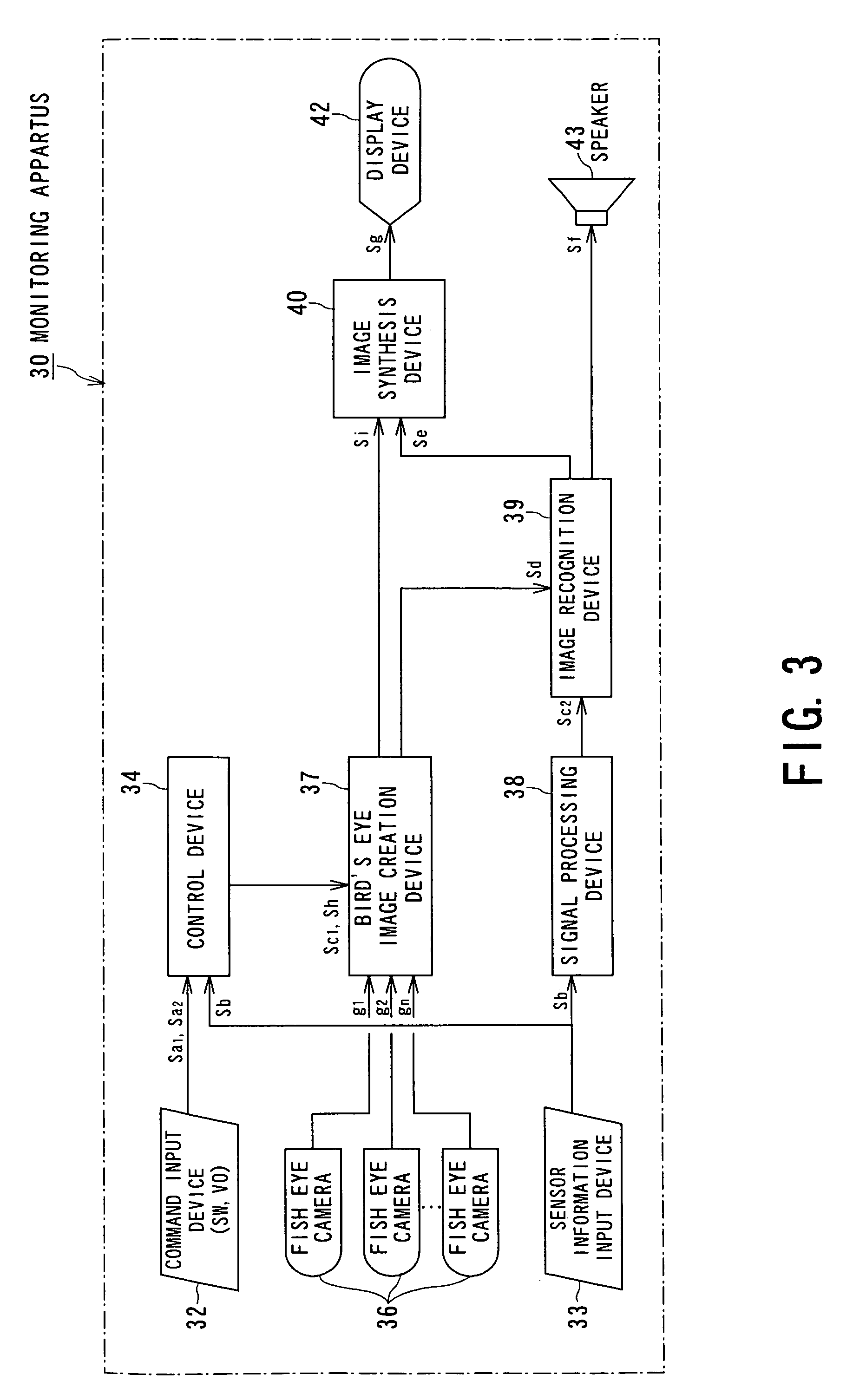
A monitoring apparatus for providing the driver with the image of blind-spot areas of a moving body. The monitoring apparatus includes: at least one of fish-eye camera mounted on a moving body, to image fish-eye image around the moving body; a dewarping unit configured to convert at least part of the fish-eye image obtained by the fish-eye camera into a two-dimensional image using a dewarping parameter; a conversion parameter calculation unit configured to calculate a conversion parameter for obtaining a bird's-eye view image from the two-dimensional image, showing an image from a hypothetical position looking down on the moving body; a bird's-eye view image creation unit configured to create a bird's-eye view image by sequentially fetching position data corresponding to each pixel of the bird's-eye view image using the conversion parameter and the dewarping conversion parameter; and a display device to display the bird's-eye view image created by the image creation unit.

Description

CROSS REFERENCE TO RELATED APPLICATIONS [0001] The application is based upon and claims the benefit of priority from the prior Japanese Patent Application No.2004-229945 ,filed on Aug. 5, 2004, the entire contents of which is incorporated herein by reference. BACKGROUND OF THE INVENTION [0002] 1. Field of the Invention [0003] The present invention relates to a monitoring technique around a moving body such as a vehicle, etc., around which fish-eye cameras mounted on the moving body monitor. More particularly, the present invention relates to a monitoring apparatus around a moving body and a method of displaying a bird's-eye view image, for obtaining a bird's-eye view image based on the images picked up by fish-eye cameras in order to ensure safe driving for the driver. [0004] 2. Description of the Related Art [0005] Up to now, a monitoring apparatus used for a moving body has been using an image processing technique for generating a composite image based on the images picked up by a...

Claims


Application Information

Patent Timeline
IPC IPC(8): G06K9/00B60R1/00G03B37/04G06T1/00G06T3/00G06T15/20H04N5/225H04N7/18
CPCB60R1/00B60R2001/1253B60R2300/105B60R2300/207B60R2300/30G06T5/006B60R2300/402B60R2300/607B60R2300/802B60R2300/8093G06T3/0018B60R2300/302G06T3/047G06T5/80B60R1/27
Inventor OZAKI, NOBUYUKI
Owner KK TOSHIBA
Learn More