
Source driver and its compression and transmission method

a source driver and compression and transmission technology, applied in static indicating devices, cathode-ray tube indicators, instruments, etc., can solve the problems of increased fabrication costs and difficult design of high integration devices, and achieve the effect of reducing fabrication costs

Inactive Publication Date: 2006-02-09
MAGNACHIP SEMICONDUCTOR LTD
View PDF13 Cites 8 Cited by
  • Summary
  • Abstract
  • Description
  • Claims
  • Application Information

AI Technical Summary

Benefits of technology

[0010] It is, therefore, an object of the present invention to provide a source driver reducing an area occupied by plural data lines to thereby reduce the fabrication cost.

Problems solved by technology

The plural data lines of the parallel data bus occupy too large area to be implemented at inside of the semiconductor device and, therefore, make it hard to design a high integration device.
Further, a fabrication cost is also increased.

Method used


Image

  • Source driver and its compression and transmission method
  • Source driver and its compression and transmission method
  • Source driver and its compression and transmission method

Examples


Embodiment Construction

[0022] Hereinafter, a source driver for use in an active matrix liquid crystal display (LCD) in accordance with the present invention will be described in detail referring to the accompanying drawings.

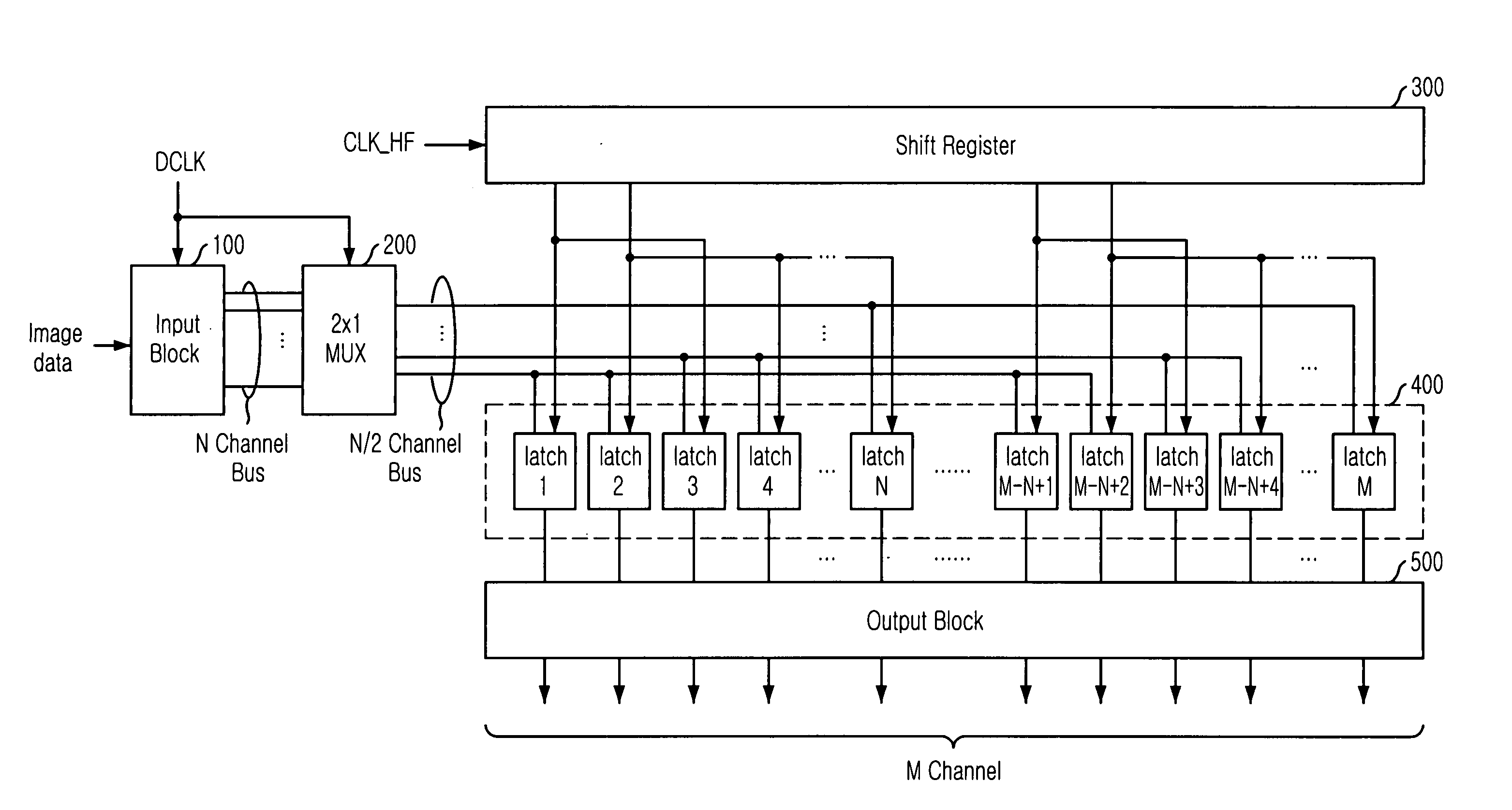
[0023]FIG. 3 is a block diagram describing a source driver for an active matrix LCD in accordance with a preferred embodiment of the present invention.

[0024] As shown, the source driver includes an input block 100, a multiplexer (MUX) 200, a shift register 300, a line latch circuit 400, and an output block 500.

[0025] The input block 100 receives a data clock DCLK and an image data to thereby generate a pixel data sequence. The pixel data sequence has plural pixel data transmitted through N channels as a continuously outputted data unit. The MUX 200 compresses the N channels of pixel data to thereby output N / 2 channels of pixel data by performing a time multiplexing. The shift register 300 receives a half clock CLK_HF to thereby output a latch enable signal to the line latch circuit ...


PUM


Abstract

The source driver for use in an active matrix liquid crystal display includes an input block for generating a pixel data sequence having pixel data transmitted through N numbers of channels as a unit pixel data, a multiplexing block for compressing the pixel data sequence to thereby output through a data bus having data lines corresponding to N / L numbers of channels, a shift register for generating a latch enable signal, and a line latch circuit constituted M numbers of latches receiving the pixel data inputted when the corresponding latch enable signal is inputted, wherein L, M, N are natural numbers, N is multiple number of L, and M is lager than N.

Description

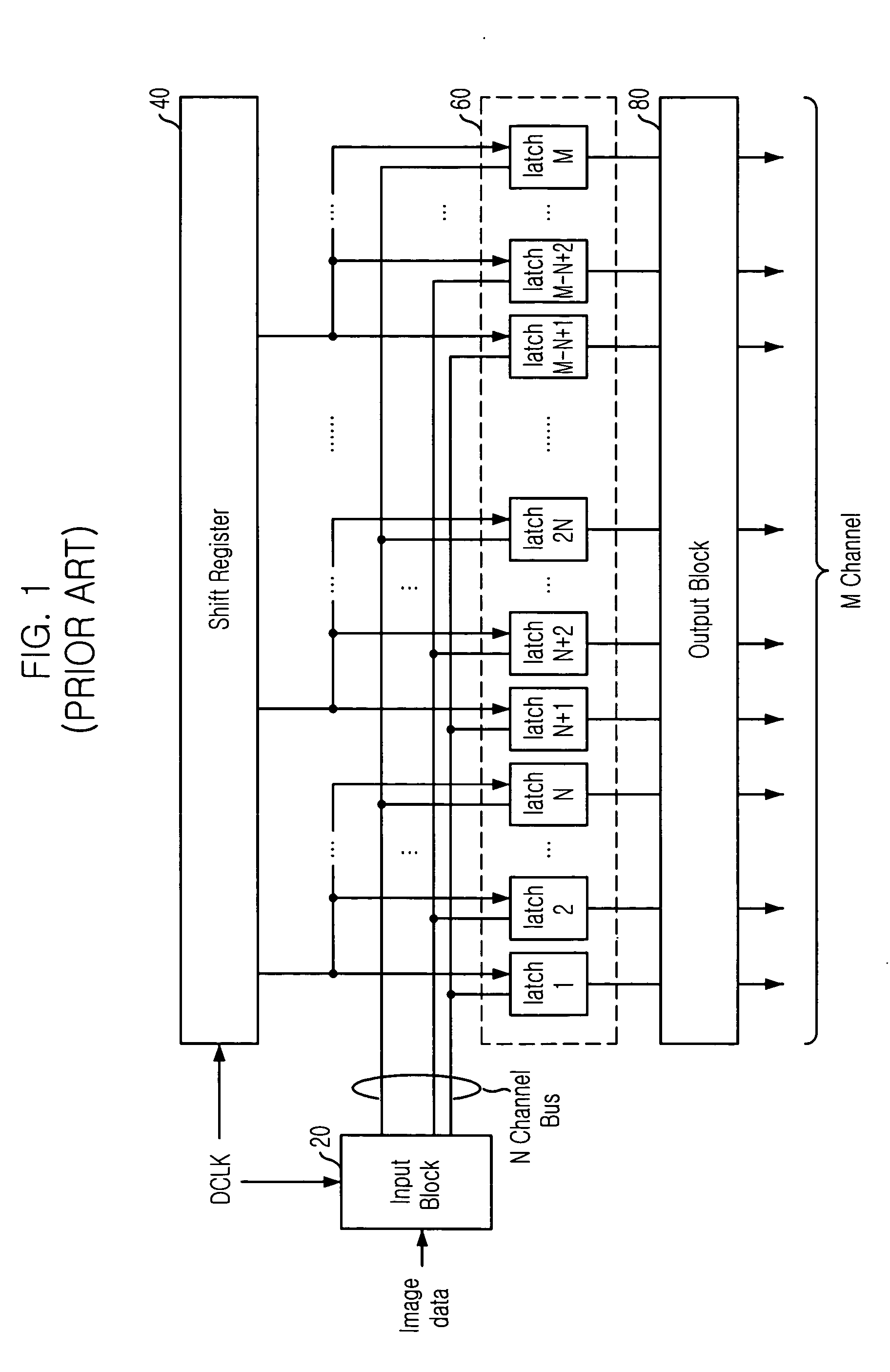
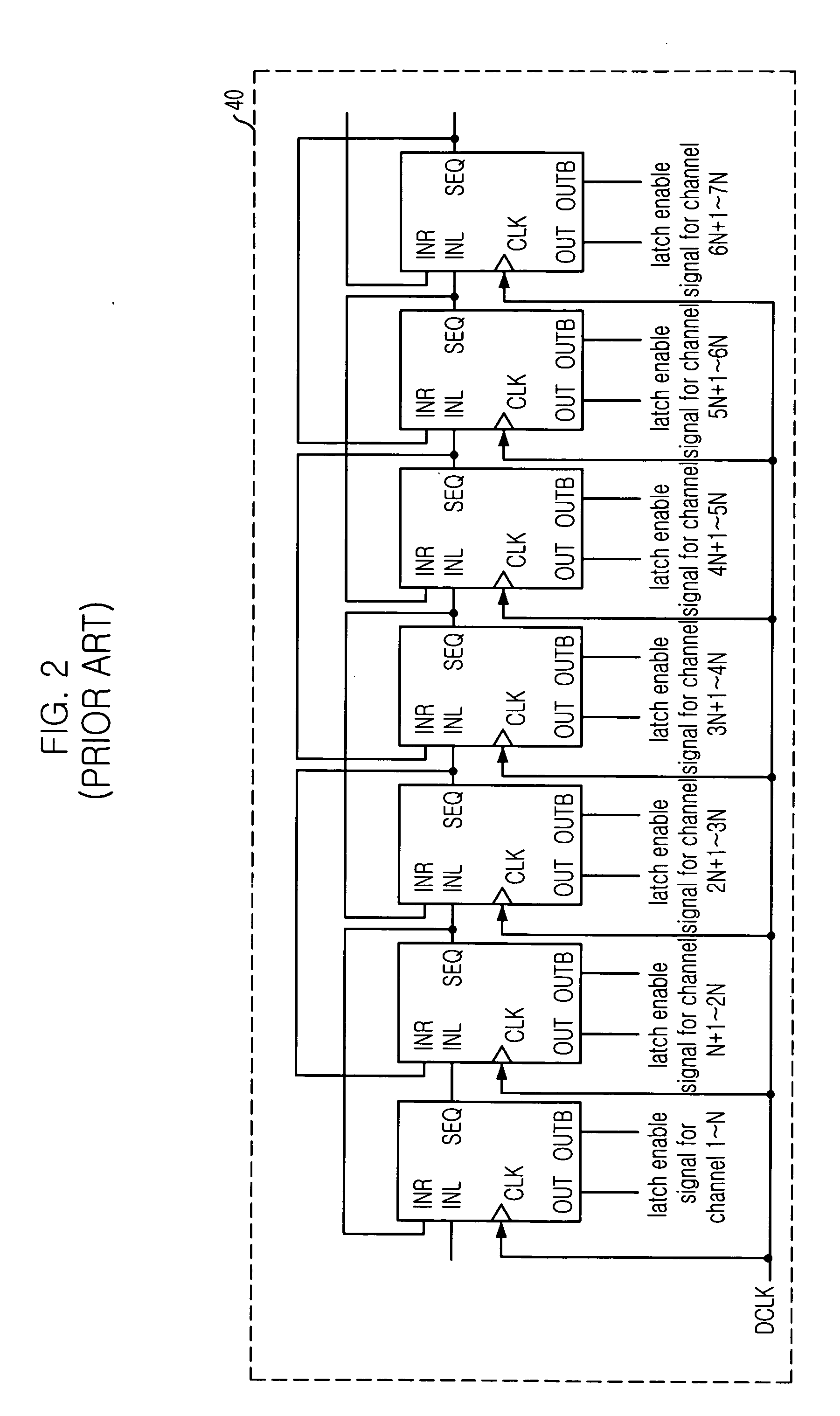
FIELD OF INVENTION [0001] The present invention relates to a delay locked loop (DLL) device; and, more particularly, to a DLL device which synchronizes an internal clock signal with an external clock signal. DESCRIPTION OF PRIOR ART [0002] Generally, a source driver for use in a flat panel display (FPD) has been known that provides a data to a panel during one fame time. The source driver is usually called as a data driver or a column driver because the source driver drives a column line of the panel. [0003] There are two methods for driving the source driver: a passive matrix (PM) and an active matrix (AM). The active matrix contains a thin film transistor (TFT) as a switch and a storage capacitor for storing data in each pixel. The TFT stores the electrical state of each pixel on the panel while all the other pixels are being updated. The active matrix provides a much brighter and sharper display than does the passive matrix with the same size. [0004]FIG. 1 is a block diagram desc...

Claims


Application Information

Patent Timeline
Patent Type & Authority Applications(United States)
IPC IPC(8): G09G3/36
CPCG09G3/3688G09G2310/0297G09G5/008G09G3/20G09G3/30G09G3/36
Inventor JUNG, TAE-HO
Owner MAGNACHIP SEMICONDUCTOR LTD
Learn More