Portable device for electronic key system and portable device search system

Inactive Publication Date: 2006-02-09
DENSO CORP
View PDF8 Cites 45 Cited by
  • Summary
  • Abstract
  • Description
  • Claims
  • Application Information

AI Technical Summary

Benefits of technology

[0005] The present invention therefore has an object of enabling easy detection of a portable device as an electronic key in an electronic key system even if it is lost.
[0007] Preferably, the handy equipment displays current position information of the portable device in a display part thereof. This information may be position information (latitude, longitude) of the portable device. However, to make the position of the portable device more legible, for example, like on-vehicle navigation devices, not only is a map containing a current position of the portable device displayed, but also the current position of the portable device may be displayed so as to be identifiable by a specific mark. If the portable device calculates a current position from a received GPS signal and transmits a signal indicating the current position as a response signal, the handy equipment can immediately recognize the current position of the portable device. If the portable device transmits the contents of received GPS signals as a response signal without calculating a current position from the GPS signals, the handy equipment may calculate a current position of the portable device from the response signal.
[0008] More preferably, the handy equipment displays distance information indicating a distance from the portable device, for example, the reception strength of a response signal from the portable device without modification. In this case, if a conversion table for converting reception strength displayed in the display part to distances is prepared in advance, the user can determine a distance from the portable device from the conversion table. If the handy equipment calculates a distance from the portable device based on the reception strength of a response signal from the portable device and displays the value of the calculated distance in the display part as distance information, the user can know a distance from the portable device merely by seeing the display contents, with increased usability.

Problems solved by technology

As a result, the user often forgets where the portable device was put, and has difficulty in locating the lost portable device.

Method used


Image

  • Portable device for electronic key system and portable device search system
  • Portable device for electronic key system and portable device search system
  • Portable device for electronic key system and portable device search system

Examples


first embodiment

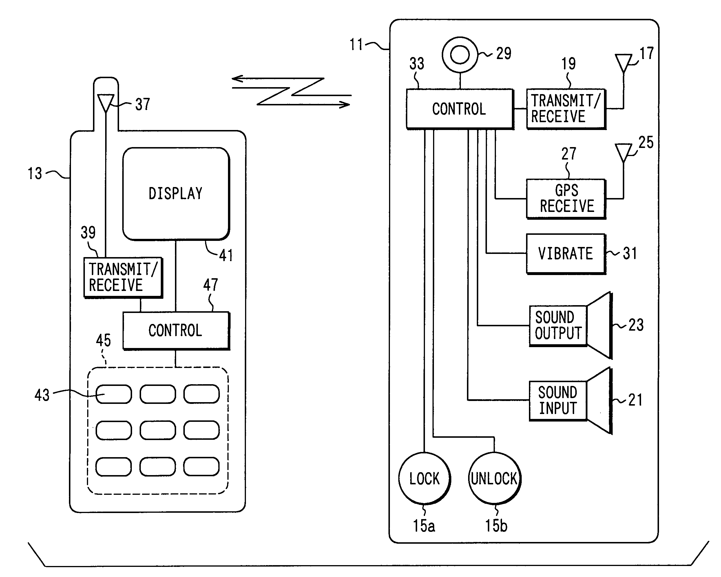
[0023] Referring first to FIG. 1, a portable device search system comprises a portable device 11 of an electronic key system of a vehicle and handy equipment 13. Both the portable device 11 and the handy equipment 13 are held by a user. The handy equipment 13 is separate from the portable device 11. The handy equipment 13, which is mobile equipment such as a cellular phone and PDA in this embodiment, may be any handy equipment such as a remote controller for other equipments such as television sets and air conditioners, or a remote controller dedicated to the search system.

[0024] The functions of the electronic key system (functions of a smart key system and RKE) in which the portable device 11 is used will be summarized though well-known. A vehicle has: a transmitter (on-vehicle transmitter) that transmits a transmission request signal to a wireless communication area around the vehicle; a receiver (on-vehicle receiver) that receives radio waves from the portable device 11; and a ...

second embodiment

[0074] A portable device search system according to the second embodiment is different from that of the first embodiment only in that the control part 33 of the portable device 11 performs processing of FIG. 7 to achieve a sixth search function instead of processing of FIG. 6.

[0075] As shown in FIG. 7, the control part 33 of the portable device 11 determines in S521 whether the magnitude of a sound inputted by the sound input part 21 is equal to or greater than a specified value (whether a volume equal to or greater than the specified value has been inputted), and waits until a volume equal to or greater than the specified value is inputted. On determining that a volume equal to or greater than the specified value has been inputted (S521: YES), the control part 33 proceeds to execute S523 to generate vibration in the vibration part 31 while generating a specific sound (buzzer sound) in the sound output part 23 for a specified time, and then repeats to execute S521.

[0076] Also in t...

third embodiment

[0078] As shown in FIG. 8, a portable device search system according to a third embodiment is different from that of the first embodiment in the construction of the portable device 11 as an electronic key to search for. The portable device 11 do not have the sound input part 21, sound output part 23, antenna 25 and GPS receiving part 27 for receiving GPS signals and vibration part 31. Instead, it has a photographing button 53 operated to activate the photographing part 29, and a memory part 55 for storing data for locating the portable device 11. The handy equipment 13 is the same as that of the first embodiment.

[0079] As shown in FIG. 9B, the control part 33 of the portable device 11 determines in S611 whether the photographing button 53 has been operated (pressed) by the user. On determining that the photographing button 53 has not been operated, the control part 33 proceeds to S617. On determining that the photographing button 53 has been operated (S611: YES), the control part 3...


PUM


Abstract

A portable device search system for an electronic key system is formed by a portable device and handy equipment such as a cellular phone, PDA and the like, which is separate from the portable device. When a predetermined operation is performed on the handy equipment, the handy equipment transmits a search signal. On receiving the search signal, the portable device generates a specific sound and vibration to notify the location. In addition, an image near the portable device may be transmitted to the handy equipment to be displayed on the handy equipment.

Description

CROSS REFERENCE TO RELATED APPLICATION [0001] This application is based on and incorporates herein by reference Japanese Patent Application No. 2004-231142 filed on Aug. 6, 2004. FIELD OF THE INVENTION [0002] The present invention relates to a portable device of an electronic key system and a portable device search system. BACKGROUND OF THE INVENTION [0003] An electronic key system for a motor vehicle is conventionally known. In this system, in response to a request (transmission request signal) transmitted from an on-vehicle device, a portable device as an electronic key carried by a user of a vehicle transmits a reply signal containing an identification code. If the code that the on-vehicle device receives from the portable device matches a code stored in advance in a memory of the on-vehicle device, predetermined operations such as door unlocking / locking and engine startup are performed. Such an electronic key system is generally referred to as a smart key system or a smart keyle...

Claims


Application Information

Patent Timeline
IPC IPC(8): G08B1/08G01S13/08B60R25/01B60R25/10B60R25/24B60R25/33E05B49/00H04Q9/00
CPCB60R25/24B60R2325/202H04M1/7253G01S5/0027G07C2209/63B60R2325/205H04M1/72412B60R25/33G08B3/10G08B5/22G08B21/0269G08B21/0283G08B23/00
Inventor OGINO, KENICHINAITO, HIROMICHI
Owner DENSO CORP
Why Eureka
Try Eureka