
Methods and apparatus for artificial disc replacement (ADR) insertion and other surgical procedures

a technology of artificial discs and insertion methods, applied in the field of spine surgery, can solve the problems of markedly reduced range of motion (rom) permitted by the adr, improperly placed adrs may wear quickly or loosen from the vertebral endplate (veps), and achieve the effect of ensuring accuracy and saferness

Inactive Publication Date: 2006-02-02
ANOVA
View PDF61 Cites 53 Cited by
  • Summary
  • Abstract
  • Description
  • Claims
  • Application Information

AI Technical Summary

Benefits of technology

[0008] This invention improves upon prior art methods and apparatus by making ADR insertion safer and more precise. Certain surgical instruments according to the invention include a level enabling a user to align the instrument for proper placement of a surgical implant. The implant may be an artificial disc replacement (ADR) or form parts of a total hip or other joint replacement.
[0013] Different surgical instruments include an indicator showing angular displacement or a wedge-shaped portion used for disc distraction. Also disclosed are blades designed for use with a power tool featuring a cutting edge configured such that rapid oscillation of the cutting tool reduces the pressure a user must apply the tool.

Problems solved by technology

Improper placement of an ADR may result in markedly decreased range of Motion (ROM) permitted by the ADR.
Furthermore, improperly placed ADRs may wear quickly or loosen from the Vertebral Endplates (VEPs).

Method used


Image

  • Methods and apparatus for artificial disc replacement (ADR) insertion and other surgical procedures
  • Methods and apparatus for artificial disc replacement (ADR) insertion and other surgical procedures
  • Methods and apparatus for artificial disc replacement (ADR) insertion and other surgical procedures

Examples


Embodiment Construction

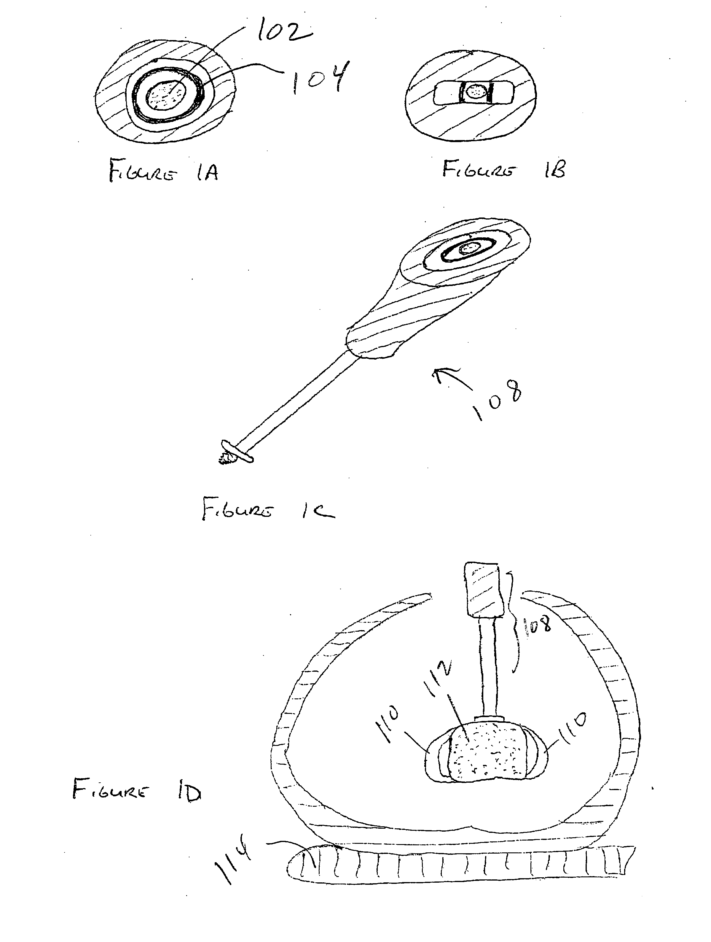
[0057]FIG. 1A is a view of the end of the handle of a surgical instrument according to the invention incorporating a bubble level. The dotted circle 102 in the center of the drawing represents a gas bubble. The dark ring 104 outside the bubble represents the target for the bubble. The level helps the surgeon align his instrument.

[0058]FIG. 1B is a view of the end of the handle of a surgical instrument with an alternative embodiment of the level. FIG. 1C is an oblique view of a surgical instrument 108 and the embodiment of the level drawn in FIG. 1A. FIG. 1D is an axial cross section of the body, a disc 110, an ADR 112, an operating room (OR) table 114, and the instrument 108 drawn in FIG. 1C. Using the level, the surgeon can assure his instrument, and the attached ADR, are perpendicular to the OR table. Thus, as long as the patient is lying properly on the OR table, and the patient does not have a rotational abnormality of the spine, the novel instrument assures the ADR is placed w...


PUM


Abstract

Improved methods and apparatus render ADR insertion safer and more precise. Certain surgical instruments according to the invention include a level enabling a user to align the instrument for proper placement of a surgical implant. A different surgical instrument includes two or more scopes mounted relative to the instrument permitting a user to simultaneously view more than one side of the instrument. A device for use with a surgical instrument having a long shaft includes a holder that surrounds at least a portion of the shaft allowing a user to control the instrument with both hands. A further surgical instrument comprises a set of retractors and one or more guards placed over the retractors for protecting the great vessels, nerves or other delicate structures during a surgical procedure. Surgical apparatus according to the invention comprises a platform mountable to an operating room table over a patient undergoing a surgical procedure, enabling a user to place their hands or attach an instrument while operating. Different surgical instruments include an indicator showing angular displacement or a wedge-shaped portion used for disc distraction. Also disclosed are blades designed for use with a power tool featuring a cutting edge configured such that rapid oscillation of the cutting tool reduces the pressure a user must apply the tool.

Description

REFERENCE TO RELATED APPLICATION [0001] This application claims priority from U.S. Provisional Patent Application Ser. No. 60 / 589,752, filed Jul. 21, 2004, the entire content of which is incorporated herein by reference.FIELD OF THE INVENTION [0002] This invention relates generally to spine surgery and, in particular, to improved methods and apparatus for artificial disc replacement (ADR) insertion. BACKGROUND OF THE INVENTION [0003] Eighty-five percent of the population will experience low back pain at some point. Fortunately, the majority of people recover from their back pain with a combination of benign neglect, rest, exercise, medication, physical therapy, or chiropractic care. A small percent of the population will suffer chronic low back pain. The cost of treatment of patients with spinal disorders plus the patient's lost productivity is estimated at 25 to 100 billion dollars annually. [0004] Seven cervical (neck), 12 thoracic, and 5 lumbar (low back) vertebrae form the norma...

Claims


Application Information

Patent Timeline
IPC IPC(8): A61B17/60
CPCA61B17/0218A61F2002/4687A61B17/1615A61B17/1633A61B17/1659A61B17/1671A61B17/1757A61B17/320016A61B17/32002A61B17/320708A61B19/26A61B19/28A61B19/46A61B2017/00464A61B2017/0256A61B2019/467A61B2019/468A61B2019/481A61F2/4425A61F2/4611A61F2/4657A61F2002/30266A61F2002/30617A61F2002/4622A61F2002/4628A61F2002/4629A61F2002/4668A61F2230/0082A61F2250/0097A61B17/14A61B17/141A61B2090/068A61B2090/067A61B90/50A61B90/60A61B90/06A61B2090/08021
Inventor FERREE, BRET A.
Owner ANOVA
Learn More